Venturi Tube

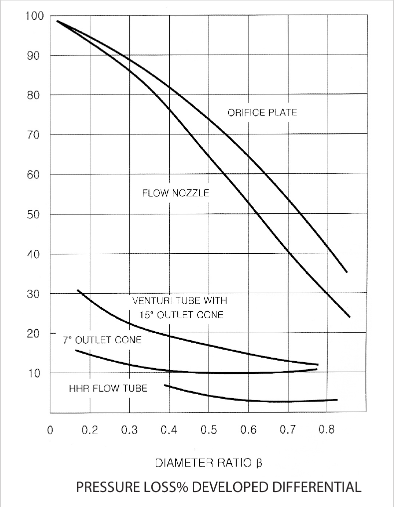
The venturi tube has a streamlined inlet and outlet. The standard design is fitted with piezometer rings (several tap holes around the circumference of the inlet and throat, enclosed by an annular ring).
When measuring non-homogeneous liquids such as slurries, the piezometer rings are usually omitted so that the pressure tap holes can be purged efficiently. The venturi tube is considered the differential-pressure primary element best suited to measuring liquids with a high solids content.
As a standard means of measurement for acceptance tests of pumps and similar equipment, an individually calibrated venturi tube has the advantage — like a calibrated orifice meter run — that the effects of tap characteristics are included in the calibration.
The standard deviation of test data for classical venturi tubes with piezometer rings at the inlet and throat is 0.3 ~ 0.4%, and properly manufactured and installed venturi tubes of this type agree with the data within ±0.75% in 95% of installations up to a pipe Reynolds number of 200,000.
The Venturi tube is streamlined at both entrance and exit. Standard designs are equipped with piezo meter rings (i.e., multiple tap holes around the periphery of inlet and throat, surrounded by an annular ring). For measurement of slurries and similar nonhomogenous liquids, the piezo meter rings are usually eliminated to permit efficient purging of the pressure tap holes. The Venturi tube is considered the best type of head meter primary device for measuring liquids containing large concentrations of solids. As a standard measurement for acceptance tests on pumping and similar equipment, the individually calibrated Venturi tube has certain advantages. Like a calibrated orifice meter run, the calibration includes the effect of tap characteristics. The standard deviation of the test data, on classical type Venturi tubes with piezo meter rings at inlet and throat connections, is between 0.3 and 0.4%. The coefficients of properly constructed and installed Venturi tubes of this type should agree with the data within ±0.75% on any pipe Reynolds number down to 200,000 on 95% of the installations.
Differential-pressure structure and flow relationship

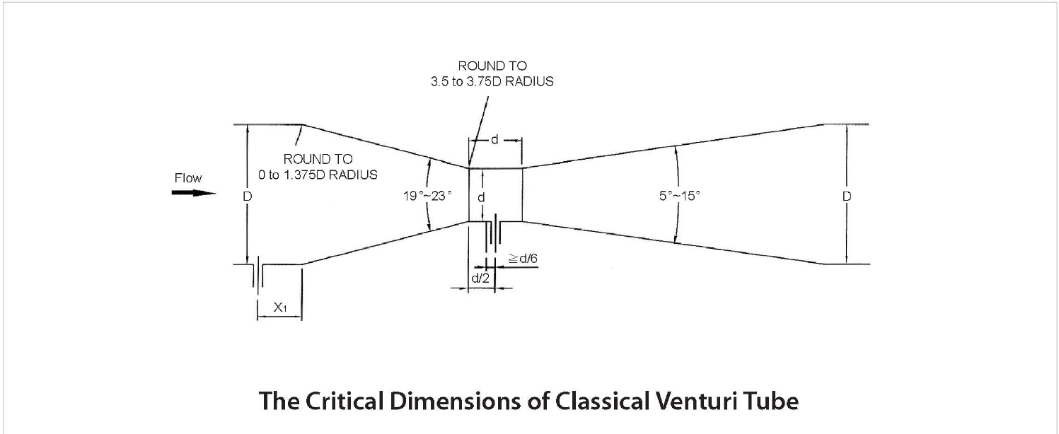
The classical venturi tube consists of an inlet cylinder → convergent section (19° ~ 23°) → cylindrical throat (throat, diameter d) → divergent section (5° ~ 15°). The junction between the inlet cylinder and the convergent section is rounded with a radius of 0 ~ 1.375D, and that between the convergent section and the throat with a radius of 3.5 ~ 3.75D.
The high-pressure tap is located in the inlet cylinder (position X₁) and the low-pressure tap at d/2 from the start of the throat; flow is obtained from the differential pressure between the two taps.
Specification comparison by model


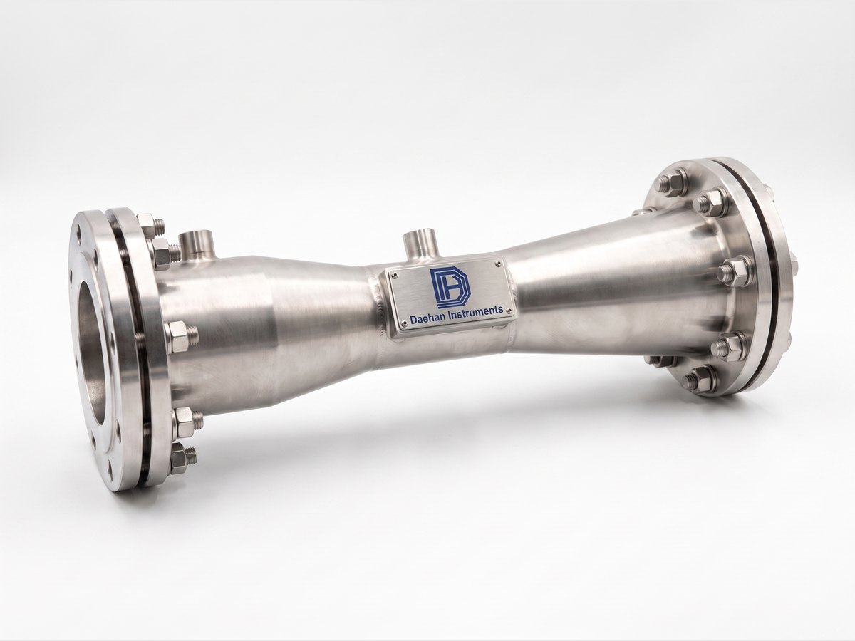
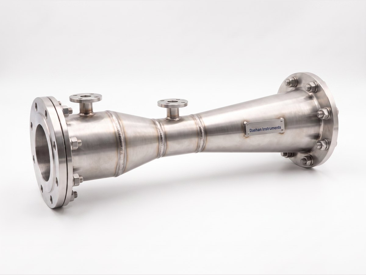
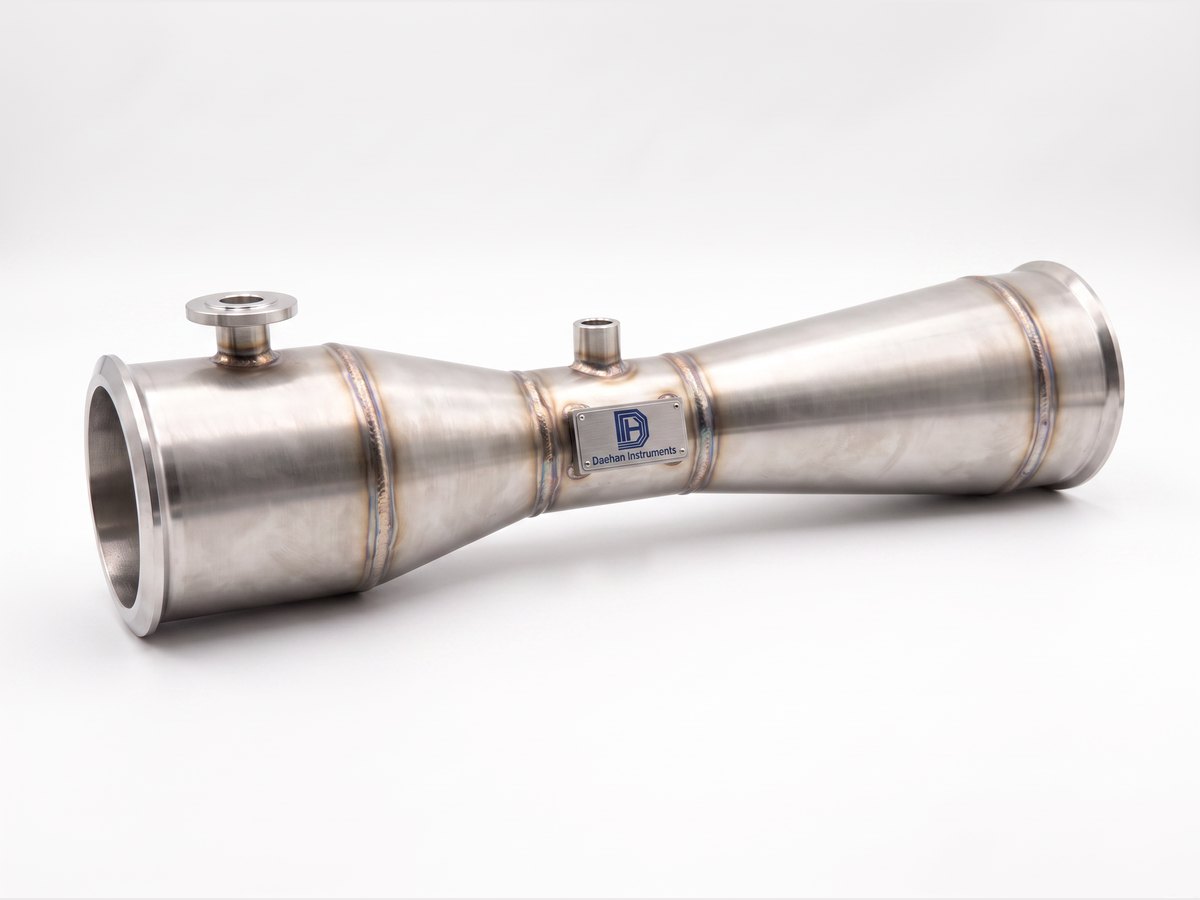
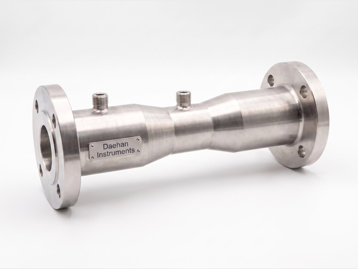
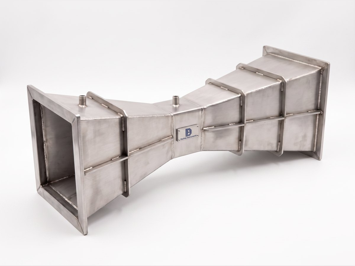
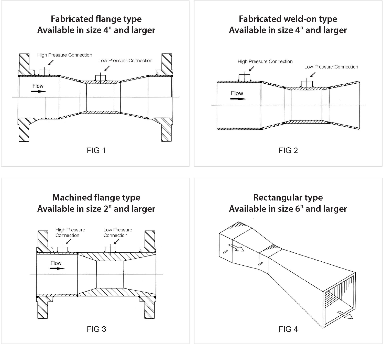
Photographic examples by type (produced from the drawings). Actual dimensions and flange ratings follow the order specification.

| Item | DHOV-FF Fabricated from welded plate · flanged connection | DHOV-FW Fabricated from welded plate · welded connection | DHOV-MF Machined · flanged connection | DHOV-MW Machined · welded connection | DHOV-RE Welded steel plate · rectangular duct type |
|---|---|---|---|---|---|
| Features | Welding sheet plate type, Flange mounting type (Fabricated flange type, FIG 1 · 4" and above) | Welding sheet plate type, Welding mounting type (Fabricated weld-on type, FIG 2 · 4" and above) | Machinery processing type, Flange mounting type (Machined flange type, FIG 3 · 2" and above) | Machinery processing type, Welding mounting type (Machined weld-on type) | Welding steel plate type, Rectangle (Rectangular type, FIG 4 · 6" and above) |
| Turndown | 6:1 | 6:1 | 6:1 | 6:1 | 6:1 |
| Materials | Carbon Steel, STS304, STS316, Inconel, Monel, Hastelloy | Carbon Steel, STS304, STS316, Inconel, Monel, Hastelloy | Carbon Steel, STS304, STS316, Inconel, Monel, Hastelloy | Carbon Steel, STS304, STS316, Inconel, Monel, Hastelloy | Carbon Steel, STS304, STS316, Inconel, Monel, Hastelloy |
| Connection | Flange 150#, 300# | Flange 150#, 300# | Flange 150#, 300#, 600#, 900#, 1500#, 2500# | Flange 150#, 300#, 600#, 900#, 1500#, 2500# | Duct |
| Applicable piping | 4B and above (100A and above) Pipe & Duct | 4B and above (100A and above) Pipe & Duct | 2B ~ 14B (50A ~ 300A) Pipe | 2B ~ 14B (50A ~ 300A) Pipe | 6B and above (150A and above) Duct |
| Standards | ISO5167-4 | ISO5167-4 | ISO5167-4 | ISO5167-4 | ISO5167-4 |
| Accuracy | ±2.0% | ±2.0% | ±1.0% | ±1.0% | ±2.0% |
Detailed conditions are confirmed at quotation.
| Item | Value |
|---|---|
| Accuracy | ±2.0% (DHOV-FF / FW / RE) · ±1.0% (DHOV-MF / MW) |
| Turndown | 6:1 |
| Venturi tube types | Fabricated flange type (FIG 1) · Fabricated weld-on type (FIG 2) · Machined flange type (FIG 3) · Rectangular type (FIG 4) |
| Minimum size by type | Fabricated flange / weld-on: 4" and above · Machined flange: 2" and above · Rectangular: 6" and above |
| Flow calculation standard | ISO5167, JIS Z 8762, ASME, KS A 0612 |
| Flange rating | ANSI 150, 300, 600, 900, 1500LB |
| Applicable pipe sizes | 4 to 72B (100A to 1800A) |
| Materials | Carbon Steel · 304SS, 304L SS, 316SS, 316L SS · Ni, Cr, Mo Alloy Steel (A182 F11 to 91) |
| Pressure tap construction | Standard: piezometer rings (multiple taps around the inlet and throat + annular ring) · slurries and non-homogeneous liquids: rings omitted (easy tap purging) |
| DP tap connection | NPT 1/2 · NPT 3/4 · SW 1/2 · SW 3/4 |
| Principal profile dimensions | Inlet radius 0 ~ 1.375D · convergent angle 19° ~ 23° · throat radius 3.5 ~ 3.75D · divergent angle 5° ~ 15° · throat tap position d/2 |

Unit: mm. Actual manufacturing dimensions are based on the approved drawing.
| β | Single 90° bend *) | Two or more 90° bends in the same plane *) | Two or more 90° bends in different planes *) **) | Reducer 3D to D over a length of 3.5D | Expander 0.75D to D over a length of D | Full bore ball or gate valve fully open |
|---|---|---|---|---|---|---|
| 0.30 | 0.5 ***) | 1.5 (0.5) | (0.5) | 0.5 ***) | 1.5 (0.5) | 1.5 (0.5) |
| 0.35 | 0.5 ***) | 1.5 (0.5) | (0.5) | 1.5 (0.5) | 1.5 (0.5) | 2.5 (0.5) |
| 0.40 | 0.5 ***) | 1.5 (0.5) | (0.5) | 2.5 (0.5) | 1.5 (0.5) | 2.5 (1.5) |
| 0.45 | 1.0 (0.5) | 1.5 (0.5) | (0.5) | 4.5 (0.5) | 2.5 (1) | 3.5 (1.5) |
| 0.50 | 1.5 (0.5) | 2.5 (1.5) | (8.5) | 5.5 (0.5) | 2.5 (1.5) | 3.5 (1.5) |
| 0.55 | 2.5 (0.5) | 2.5 (1.5) | (12.5) | 6.5 (0.5) | 3.5 (1.5) | 4.5 (2.5) |
| 0.60 | 3.0 (1.0) | 3.5 (2.5) | (17.5) | 8.5 (0.5) | 3.5 (1.5) | 4.5 (2.5) |
| 0.65 | 4.0 (1.5) | 4.5 (2.5) | (23.5) | 9.5 (1.5) | 4.5 (2.5) | 4.5 (2.5) |
| 0.70 | 4.0 (2.0) | 4.5 (2.5) | (27.5) | 10.5 (2.5) | 5.5 (3.5) | 5.5 (3.5) |
| 0.75 | 4.5 (3.0) | 4.5 (3.5) | (29.5) | 11.5 (3.5) | 6.5 (4.5) | 5.5 (3.5) |
Values without parentheses are 'zero additional uncertainty' values; values in parentheses are '0.5% additional uncertainty' values. *) The radius of curvature of the bend must be at least the pipe diameter. **) Since the effect may remain even beyond 40D, no value without parentheses is given. ***) Since no fitting may be placed within 0.5D of the venturi upstream pressure tap, only the 'zero additional uncertainty' value applies. Straight runs are measured from the plane of the venturi upstream pressure tap, and over lengths beyond those stated in the table the pipe roughness must not exceed that of commercially available smooth pipe (k/D ≤ 10⁻³). On the downstream side, fittings and disturbances located at least 4 throat diameters from the plane of the throat pressure tap do not affect measurement accuracy.
Straight run and installation notes
You can request a quotation by combining the model codes.
| FF | Fabricated flange type (fabricated from plate · flanged) |
| FW | Fabricated weld-on type (fabricated from plate · welded) |
| MF | Machined flange type (machined · flanged) |
| MW | Machined weld-on type (machined · welded) |
| RE | Rectangular type (rectangular duct) |
| □□□ | Pipe size in inch or mm (nominal pipe size, inch or mm) |
| CS | Carbon Steel |
| 4S | 304SS |
| 4L | 304L SS |
| 6S | 316SS |
| 6L | 316L SS |
| 11 | A182 F11 |
| 22 | A182 F22 |
| 51 | A182 F51 |
| 91 | A182 F91 |
| OP | Option |
| 015 | ANSI Class 150 LB |
| 030 | ANSI Class 300 LB |
| 060 | ANSI Class 600 LB |
| 090 | ANSI Class 900 LB |
| 150 | ANSI Class 1500 LB |
| 250 | ANSI Class 2500 LB |
| 000 | Option |
| 1 | NPT 1/2 |
| 2 | NPT 3/4 |
| 3 | SW 1/2 |
| 4 | SW 3/4 |
| /□□□ | Options (by separate agreement) |
Product Catalog PDF
Printable datasheet with the specifications, dimensions and ordering information on this page (same content as the web page, generated automatically)
Description · specifications · type drawings (FIG 1~4) · principal dimensions · required straight run table · ordering codes · 4 pages
p.12 Venturi Tube DHOV-FF / FW / MF / MW / RE· 23p
Other models in the same product family
Tell us the pipe size, fluid, pressure / temperature and flow range, and we will propose a suitable model and a flow calculation sheet.
Contact us online ✉ [email protected] (Sales)Tel 031-357-8431 (Sales, ext. 1) · Fax 031-357-8432