Venturi · Nozzle

Venturi Nozzle Venturi Nozzle

MODEL : DHOV-N-TM / DHOV-N-TF / DHOV-N-BW / DHOV-N-FL
A venturi nozzle consisting of an axisymmetric convergent section with the same upstream face as the ISA 1932 nozzle, a cylindrical throat and a divergent section. Supplied in threaded, butt weld and flanged connection types, with flow calculated in accordance with ISO 5167-3.

Product Overview

Venturi Nozzle
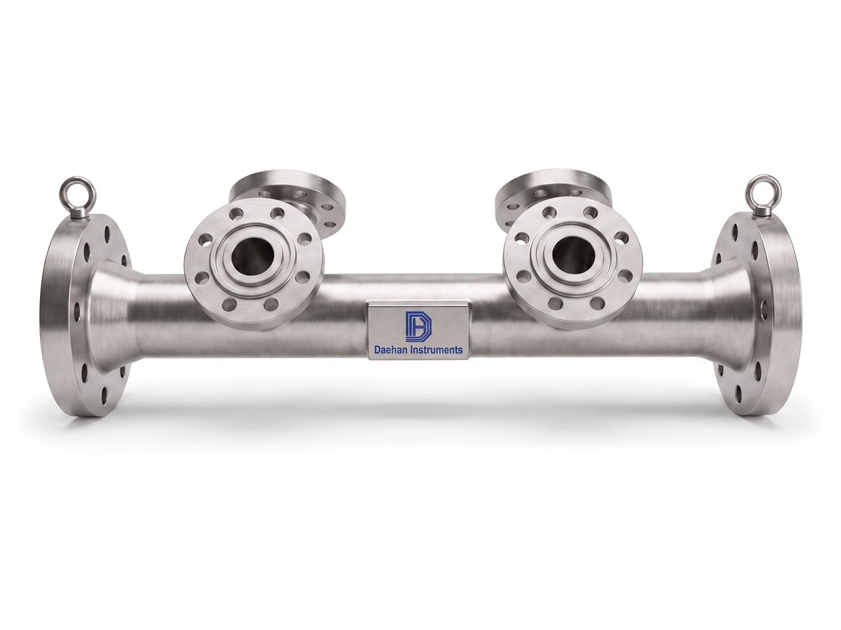
Venturi Nozzle DHOV-N (flanged type)
DHOV-N-TMDHOV-N-TFDHOV-N-BWDHOV-N-FL

The venturi nozzle is axisymmetric in profile and consists of a convergent section with a rounded profile, a cylindrical throat (throat) and a divergent section. The upstream face is identical to the ISA 1932 nozzle. The throat consists of a section E of length 0.3d, the same as the ISA 1932 nozzle, and a section E′ of length 0.4d ~ 0.45d.

The throat diameter d is the mean of at least four diameter measurements distributed at approximately equal angles in axial planes. The throat must be cylindrical, and no diameter in any cross-section may deviate from the mean diameter by more than 0.05%. The divergent section joins section E of the throat without rounding, but burrs (burr) are removed.

The included angle Φ of the divergent section is 30° or less, and the venturi nozzle may be truncated (truncate) in the same way as the classical venturi tube.

0.5B ~ 120B (15A ~ 3000A)ANSI 150 ~ 1500LBAccuracy ±2.0%ISO 5167-3
English description

The profile of the Venturi nozzle is axisymmetric. It consists of a convergent section, with a rounded profile, a cylindrical throat and a divergent. The upstream face is identical with that of an ISA 1932 nozzle. The Throat consists of a part E of length 0.3d which is the same as for the ISA 1932 nozzle and a part E' of a length 0.4d to 0.45d. The value d of the diameter of the throat shall be taken as the mean of measurements of at least four diameters distributed in axial planes and at approximately equal angles to each other. The throat shall be cylindrical. No diameter of any cross-section shall differ by more than 0.05% from the value of the mean diameter. This requirement is considered as satisfied when the deviations in the length of any of the measured diameters comply with the said requirement in respect of deviation from the mean. The divergent section shall be connected with the part E of the throat without a rounded part, but any burrs shall be removed. The included angle of the divergent section, Φ, shall be less than or equal to 30°. The Venturi nozzle may be truncated in the same way as the classical venturi tube.
Measurement principle

Differential-pressure structure and flow relationship

The venturi nozzle consists of a convergent section with a rounded profile (upstream face identical to the ISA 1932 nozzle) → a cylindrical throat (E: 0.3d, E′: 0.4d ~ 0.45d) → a divergent section with an included angle of 30° or less.

Flow is obtained from the differential pressure between the high pressure upstream of the convergent section and the low pressure at the throat; because pressure is recovered in the divergent section, the permanent pressure loss is smaller than that of a plain nozzle of the same β.

Types · model configuration

Specification comparison by model

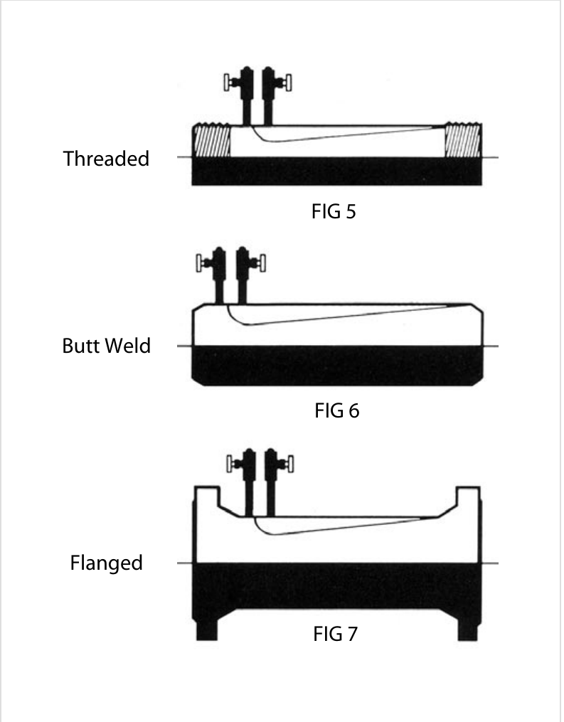
FIG 5 Threaded · FIG 6 Butt Weld · FIG 7 Flanged
ItemDHOV-N-TM
Male threaded connection
DHOV-N-TF
Female threaded connection
DHOV-N-BW
Butt weld connection
DHOV-N-FL
Flanged connection
FeaturesMale screw mounting type (Threaded type, FIG 5)Female screw mounting type (Threaded type, FIG 5)Butt welding mounting type (Butt weld type, FIG 6)Flange mounting type (Flanged type, FIG 7)
Turndown6:16:16:16:1
MaterialsCarbon Steel, STS304, STS316, Inconel, Monel, HastelloyCarbon Steel, STS304, STS316, Inconel, Monel, HastelloyCarbon Steel, STS304, STS316, Inconel, Monel, HastelloyCarbon Steel, STS304, STS316, Inconel, Monel, Hastelloy
ConnectionScrew 1/2B ~ 2B (15A ~ 50A)Screw 1/2B ~ 2B (15A ~ 50A)Butt WeldFlange 150#, 300#, 600#, 900#, 1500#, 2500#
Applicable piping1/2B ~ 2B (15A ~ 50A) Pipe1/2B ~ 2B (15A ~ 50A) Pipe2B ~ 120B (50A ~ 3000A) Pipe2B ~ 120B (50A ~ 3000A) Pipe
StandardsISO5167-3ISO5167-3ISO5167-3ISO5167-3
Accuracy±2.0%±2.0%±2.0%±2.0%

Technical Specifications

Detailed conditions are confirmed at quotation.

ItemValue
Accuracy±2.0%
Turndown6:1
Connection typeThreaded type (FIG 5) · Butt weld type (FIG 6) · Flanged type (FIG 7)
Flow calculation standardISO5167, JIS Z 8762, ASME, KS A 0612
Flange ratingANSI 150, 300, 600, 900, 1500LB
Applicable pipe sizes0.5 to 120B (15A to 3000A)
MaterialsCarbon Steel · 304SS, 304L SS, 316SS, 316L SS · Ni, Cr, Mo Alloy Steel (A182 F11 to 91)
ProfileUpstream face identical to the ISA 1932 nozzle · throat E 0.3d + E′ 0.4d ~ 0.45d · throat diameter deviation ≤ 0.05% · divergent section included angle Φ ≤ 30° · may be truncated (truncate)
DP tap connectionNPT 1/4 · NPT 1/2 · NPT 3/4 · SW 1/2 · SW 3/4

Standards

Dimensions · drawings

Unit: mm. Actual manufacturing dimensions are based on the approved drawing.

Venturi nozzle required straight run (multiples of D)

β2. Single 90° bend or tee (flow from one branch only)3. Two or more 90° bends in the same plane4. Two or more 90° bends in different planes5. Reducer 2D to D over 2 length of 1.5D to 3D6. Expander 0.5D to D over a length of D to 2D7. Globe valve full open8. Full bore ball or gate valve fully open9. Abrupt symmetrical reduction (diameter ratio ≥ 0.5)10. Thermometer pocket or well (≤ 0.03D)11. Thermometer pocket or well (0.03D ~ 0.13D)12. Downstream fittings (columns 2 to 8)
0.2010 (6)14 (7)34 (17)516 (8)18 (9)12 (6)4 (2)
0.2510 (6)14 (7)34 (17)516 (8)18 (9)12 (6)4 (2)
0.3010 (6)16 (8)34 (17)516 (8)18 (9)12 (6)5 (2.5)
0.3512 (6)16 (8)36 (18)516 (8)18 (9)12 (6)5 (2.5)
0.4014 (7)18 (9)36 (18)516 (8)20 (10)12 (6)6 (3)
0.4514 (7)18 (9)38 (17)517 (9)20 (10)12 (6)6 (3)
0.5014 (7)20 (10)40 (20)6 (5)18 (9)22 (11)12 (6)30 (15)5 (3)20 (10)6 (3)
0.5516 (8)22 (11)44 (22)8 (5)20 (10)24 (12)14 (7)6 (3)
0.6018 (9)26 (13)48 (24)9 (5)22 (11)26 (13)14 (7)7 (3.5)
0.6522 (11)32 (16)54 (27)11 (6)25 (13)28 (14)16 (8)7 (3.5)
0.7028 (14)36 (18)62 (31)14 (7)30 (15)32 (16)20 (10)7 (3.5)
0.7536 (18)42 (21)70 (35)22 (11)38 (19)36 (18)24 (12)8 (4)
0.8046 (23)50 (25)80 (40)30 (15)54 (27)44 (22)30 (15)8 (4)

Columns 2 ~ 11 are the upstream (inlet) side and column 12 is the downstream (outlet) side straight run. Values without parentheses are 'zero additional uncertainty' values; values in parentheses are '0.5% additional uncertainty' values. The minimum required straight run is the length between each upstream/downstream fitting and the primary element, and all straight lengths are measured from the upstream face of the primary element. The installation of thermometer pockets or wells does not alter the minimum upstream straight run required for other fittings.

Installation requirements

Straight run and installation notes

Ordering information (How to Order)

You can request a quotation by combining the model codes.

Model (DHOV-N-)

TMThreaded Male type
TFThreaded Female type
BWButt weld type
FLFlanged type

Nominal Pipe Size

□□□Pipe size in inch or mm (nominal pipe size, inch or mm)

Material

CSCarbon Steel
4S304SS
4L304L SS
6S316SS
6L316L SS
11A182 F11
12A182 F12
51A182 F51
91A182 F91
OPOption

Flange Connection

015ANSI Class 150 LB
030ANSI Class 300 LB
060ANSI Class 600 LB
090ANSI Class 900 LB
150ANSI Class 1500 LB
NPT □□□Threaded (threaded connection)
000Option

Diff' Taps

0NPT 1/4
1NPT 1/2
2NPT 3/4
3SW 1/2
4SW 3/4

Option

/□□□Options (by separate agreement)

Download Documents

Product Catalog PDF

View all catalogs

Related Products

Other models in the same product family

We can help with specification review and quotation

Tell us the pipe size, fluid, pressure / temperature and flow range, and we will propose a suitable model and a flow calculation sheet.

Contact us online ✉ [email protected] (Sales)

Tel 031-357-8431 (Sales, ext. 1) · Fax 031-357-8432