Annular Venturi Meter

The annular venturi meter is a patented technology that accurately measures flow over a wide range of Reynolds numbers, for a variety of conditions and fluids. It operates on the same physical principle as other differential-pressure flow meters in that it uses the principle of conservation of energy in the fluid flow within the pipe.
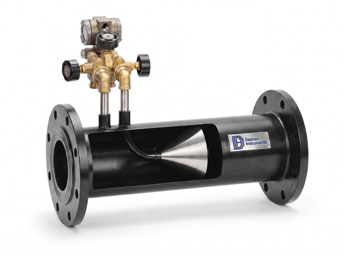
Its outstanding performance characteristics, however, come from its unique design. The cone positioned at the center of the tube interacts with the fluid, reshaping the velocity profile and creating a low-pressure region immediately downstream of the cone.
The difference between the static (line) pressure and the low pressure formed downstream of the cone is measured with two pressure taps. One tap is located slightly upstream of the cone, the other on the downstream face of the cone itself. This differential pressure is applied to the Bernoulli equation to obtain the flow rate.
Because the cone is positioned at the center of the line, the velocity profile at the measuring point is optimized, allowing accurate and reliable flow measurement regardless of upstream flow conditions.
The Annular venturi meter is a patented technology that accurately measures flow over a wide range of Reynolds numbers, under all kinds of conditions and for a variety of fluids. It operates on the same physical principle as other differential pressure-type flowmeters, using the theorem of conservation of energy in fluid flow through a pipe. The Annular venturi meter remarkable performance characteristics, however, are the result of its unique design. It features a centrally-located cone inside the tube. The cone interacts with the fluid flow, reshaping the fluid's velocity profile and creating a region of lower pressure immediately downstream of itself. The pressure difference, exhibited between the static line pressure and the low pressure created downstream of the cone, can be measured via two pressure sensing taps. One tap is placed slightly upstream of the cone, the other is located in the downstream face of the cone itself. The pressure difference can then be incorporated into a derivation of the Bernoulli equation to determine the fluid flow rate. The cone's central position in the line optimizes the velocity profile of the flow at the point of measurement, assuring highly accurate, reliable flow measurement regardless of the condition of the flow upstream of the meter.
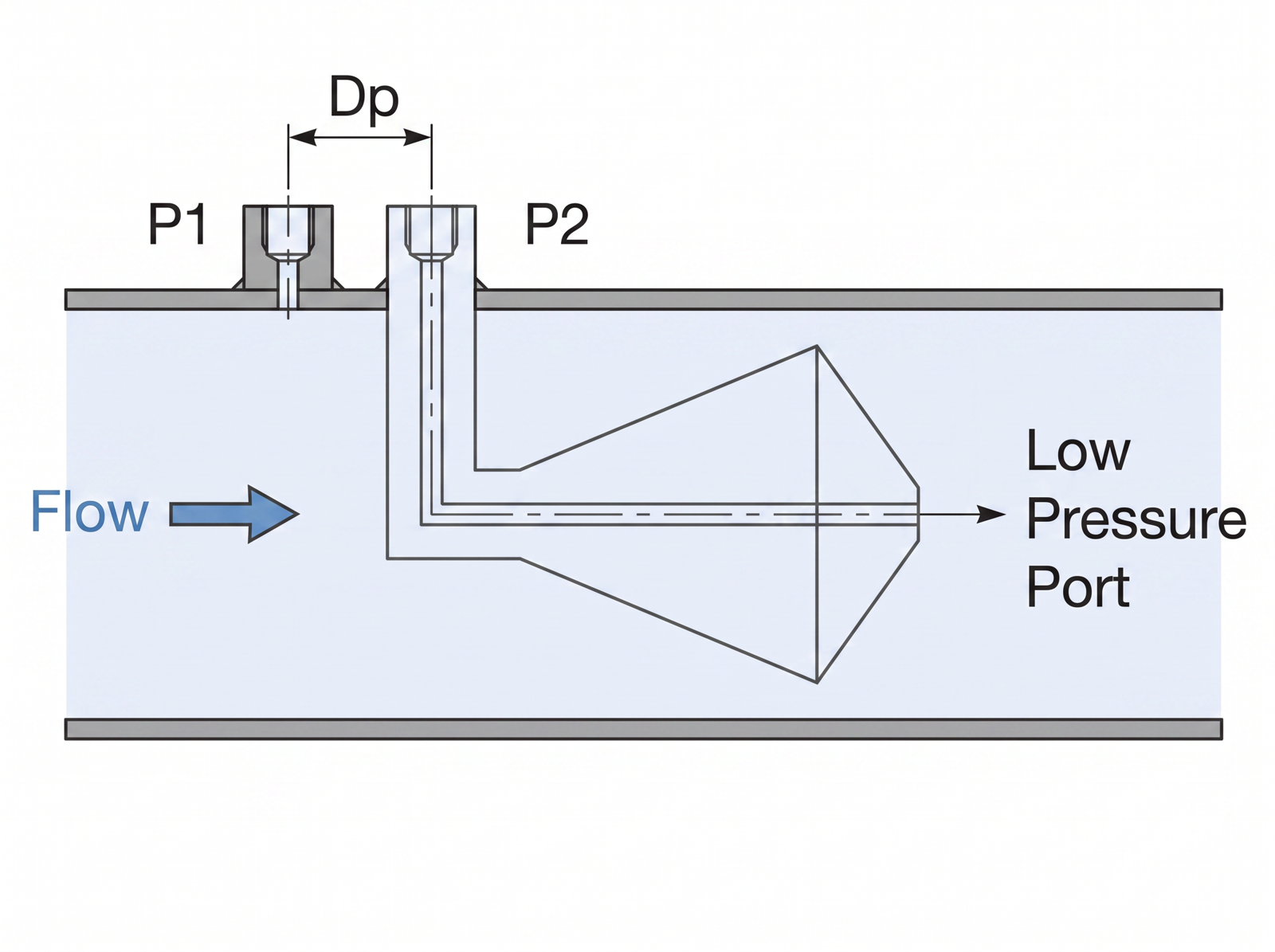
Differential-pressure structure and flow relationship

The annular venturi meter is a differential-pressure flow meter. According to Bernoulli's theorem on the conservation of energy in a closed pipe, at a constant flow rate the pressure in the pipe is inversely proportional to the square of the velocity. That is, as the velocity increases, the pressure decreases.
If the pressure of the fluid approaching the meter is P₁, the pressure drops to P₂ as the velocity increases in the cross-section narrowed by the cone (Figure 1). P₁ and P₂ are measured at the meter taps with a differential-pressure transmitter, and the differential pressure generated rises and falls exponentially with velocity. The more of the pipe cross-section the cone occupies, the greater the differential pressure generated at the same flow rate.
The β ratio is the flow area at the largest cross-section of the cone (converted to an equivalent diameter) divided by the inside diameter of the meter.
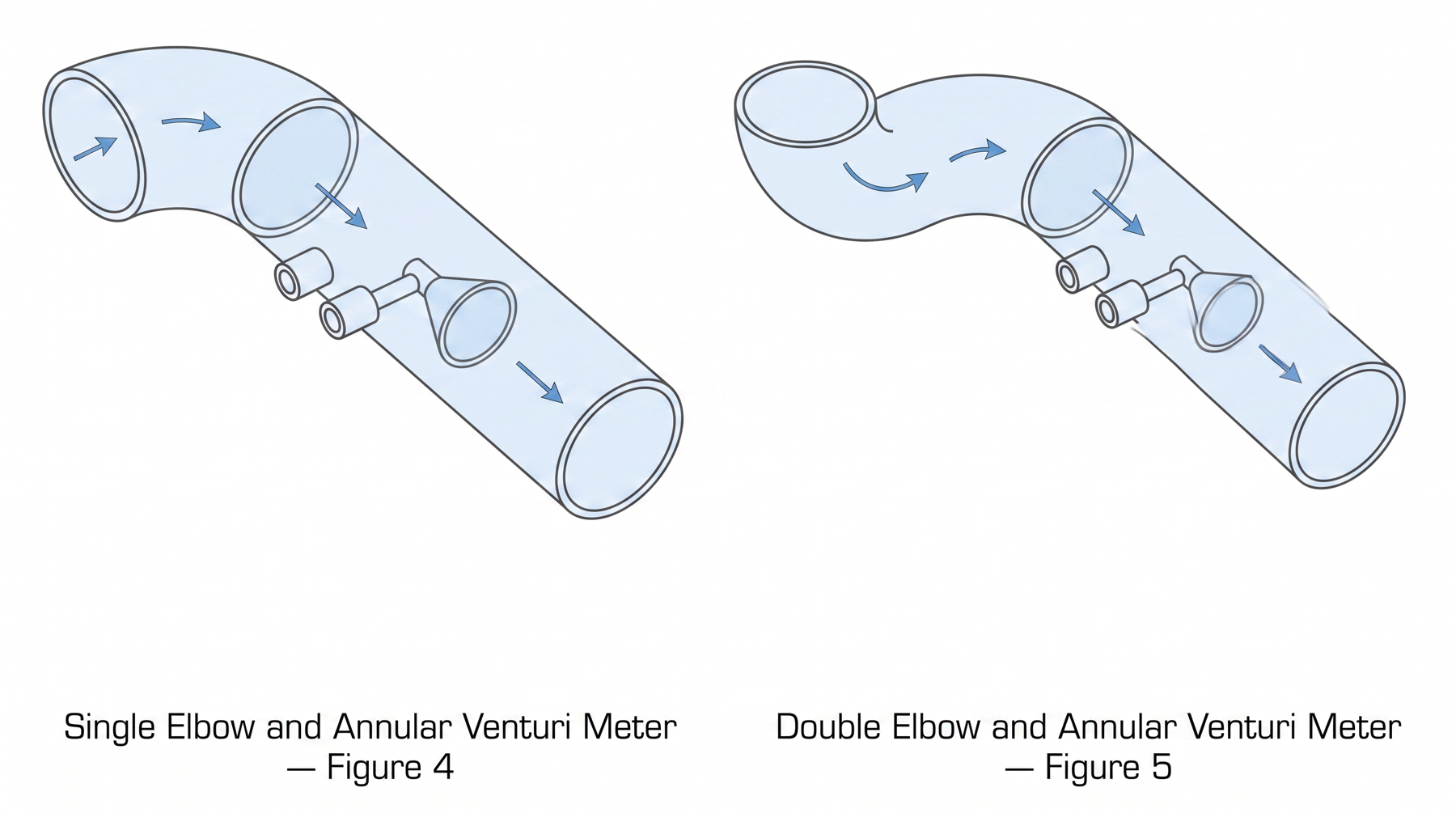
The cone interacts directly with the 'high-velocity core' at the center of the pipe, mixing it with the slower flow near the wall. As a result, even flow disturbed by elbows, valves, reducers and the like is flattened toward a well-developed velocity profile as it approaches the cone, forming a predictable velocity profile even under non-ideal conditions.
Specification comparison by model


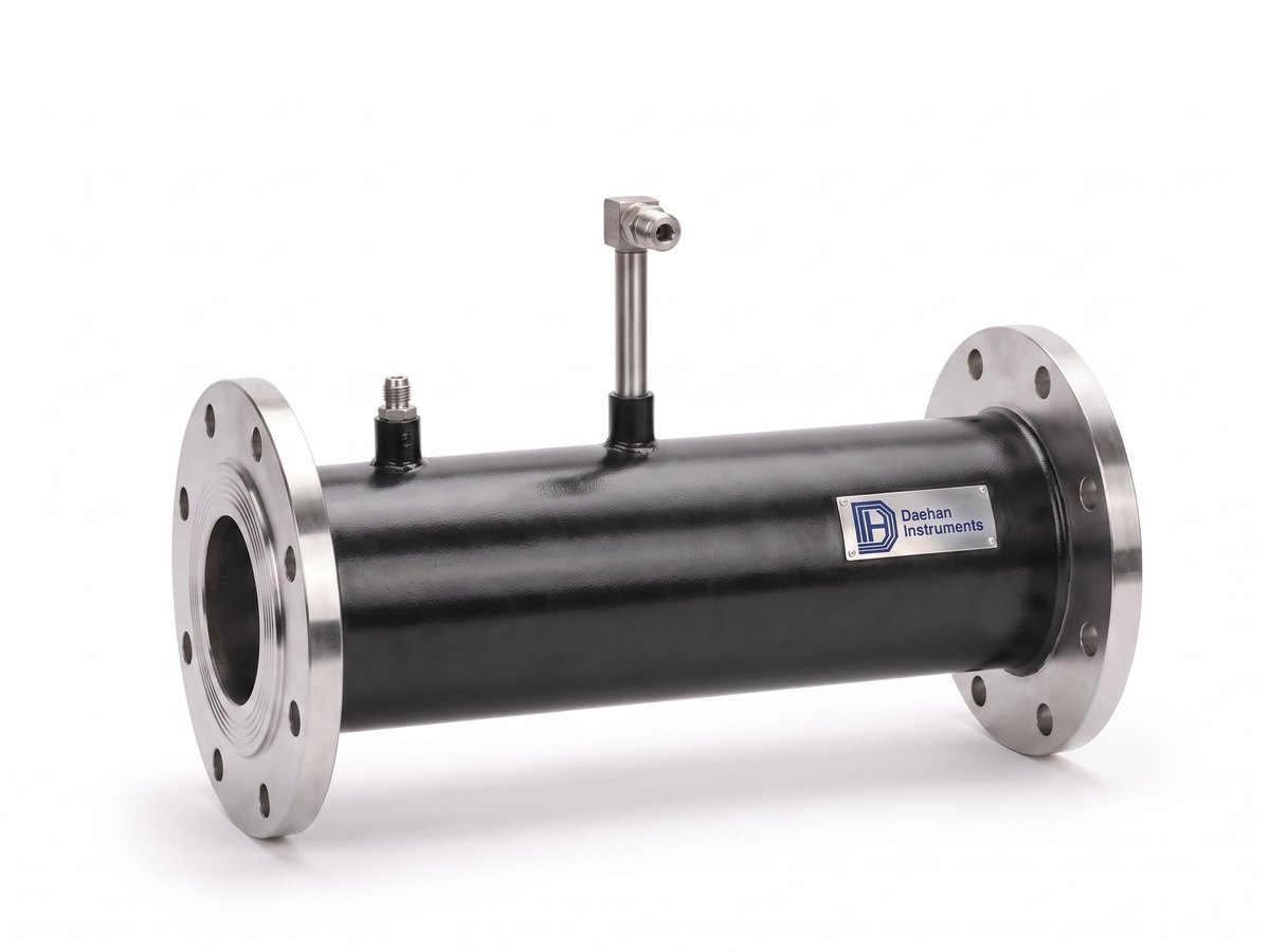
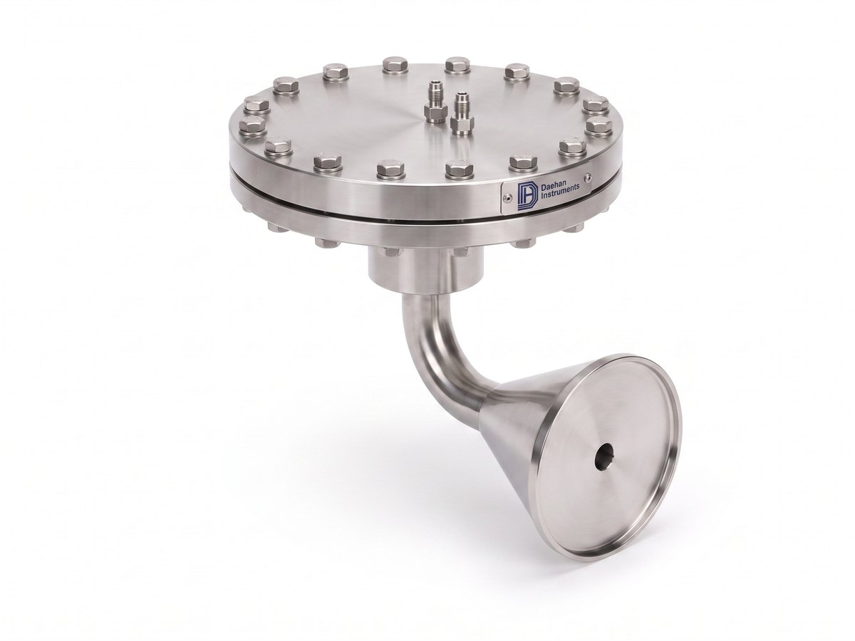
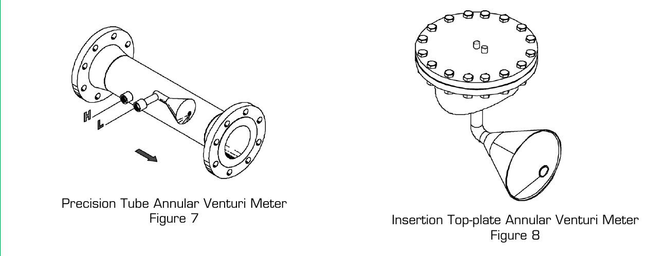
Photographic examples by type (produced from the drawings). Actual dimensions and flange ratings follow the order specification.

| Item | DHAV-CC01 Standard type · precision tube (flanged) | DHAV-CC02 Welded type · insertion top-plate |
|---|---|---|
| Features | Unnecessary direct-connecting-pipe & low pressure loss (no straight run required · low pressure loss) | Unnecessary direct-connecting-pipe & low pressure loss (no straight run required · low pressure loss) |
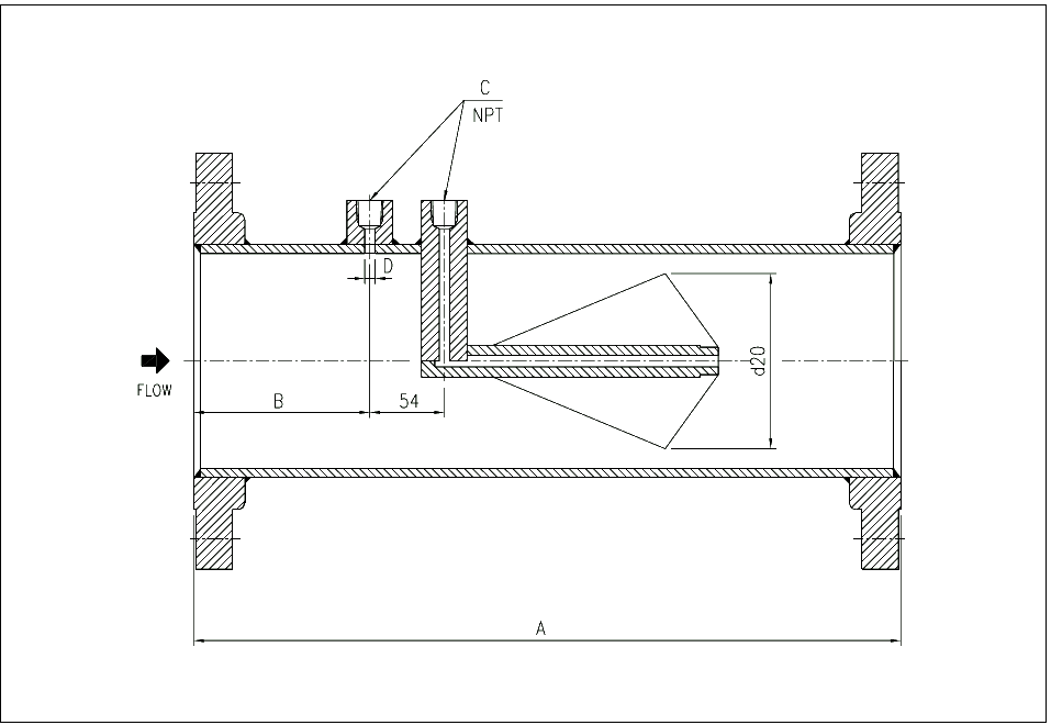
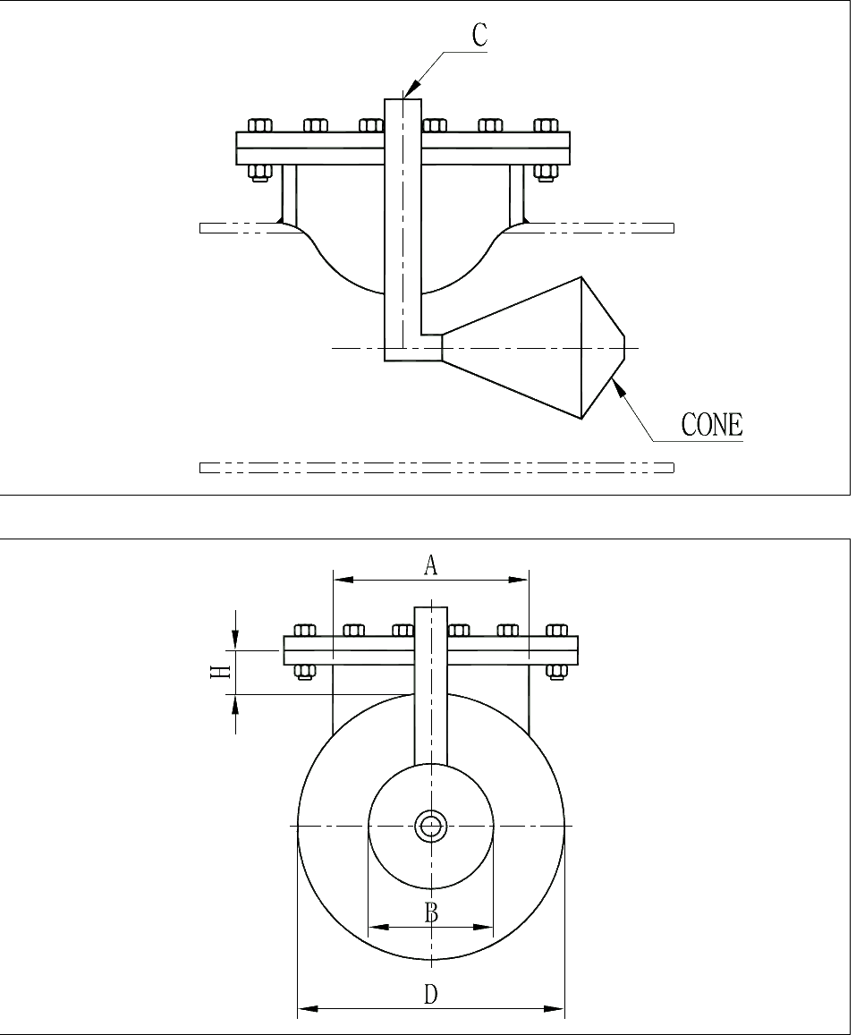
| Type | Precision Tube Annular Venturi Meter (Figure 7) · Flange version | Insertion Top-plate Annular Venturi Meter (Figure 8) · Welded type |
| Turndown | 10:1 | 10:1 |
| Materials | Cone: STS304, STS316, Inconel, Monel, Hastelloy / Body: C.S, STS304, STS316, Inconel, Monel, Hastelloy | Cone: STS304, STS316, Inconel, Monel, Hastelloy / Body: C.S, STS304, STS316, Inconel, Monel, Hastelloy |
| Connection | Flange 150#, 300#, 600# | Pipe side (top-plate welded to the pipe) |
| Applicable piping | 1/2B ~ 72B Pipe & Duct | 20B ~ 72B Pipe & Duct |
| Accuracy | ±0.5% (Calibration) | ±0.5% (Calibration) |
Detailed conditions are confirmed at quotation.
| Item | Value |
|---|---|
| Accuracy | ±0.5% of reading, primary element basis |
| Repeatability | +0.1% or better |
| Turndown | Typically 10:1 (higher is possible) · linear signal down to Re 8,000 |
| Required straight run | Upstream 0 ~ 3D · downstream 0 ~ 1D ※ Performance tests installed directly downstream of a single 90° elbow and of close-coupled double elbows (out of plane) showed that the meter can be installed adjacent to elbows without loss of accuracy |
| Standard β ratios | 0.45, 0.55, 0.65, 0.75, 0.85 |
| Applicable pipe sizes | Precision tube type 15A ~ 600A and larger · insertion top-plate type 150A ~ 1800A and larger |
| Materials | Cone: STS304, STS316, Inconel, Monel, Hastelloy / Body: C.S, STS304, STS316, Inconel, Monel, Hastelloy |
| Connection | DHAV-CC01: Flange 150#, 300#, 600# · DHAV-CC02: Pipe side |
| DP tap connection | DHAV-CC01: PT 1/4 (15 ~ 40mm) · PT 1/2 (50mm and larger) / DHAV-CC02: NPT 1/2 |
| Long-term performance | The streamlined shape of the cone does not force the fluid to impact an abrupt face, and the boundary layer pushes the fluid away from the β edge, so wear from contaminated fluids is low and the β ratio and calibration are maintained for a long time |
| Signal stability | Short vortices form as the fluid passes the cone, producing a stable signal of low amplitude and high frequency (an orifice produces long vortices → high amplitude, low frequency) |
| Permanent pressure loss | Lower than a conventional orifice plate because there is no impact against an abrupt face · the stable signal allows the recommended full-scale differential pressure to be set lower |
| Other characteristics | No stagnant zones (swept-through design prevents accumulation of debris, condensate and particles) · mixing effect from the short vortices downstream of the cone (also applied as a static mixer) |

Unit: mm. Actual manufacturing dimensions are based on the approved drawing.

| SIZE (mm) | A (mm) | B (mm) | C (PT) | C′ | REMARKS |
|---|---|---|---|---|---|
| 15 | 203 | 64 | 1/4 | 6 | 150#, 300# ANSI RF FLANGE |
| 20 | 203 | 64 | 1/4 | 6 | 150#, 300# ANSI RF FLANGE |
| 25 | 203 | 64 | 1/4 | 6 | 150#, 300# ANSI RF FLANGE |
| 40 | 254 | 76 | 1/4 | 6 | 150#, 300# ANSI RF FLANGE |
| 50 | 305 | 89 | 1/2 | 6 | 150#, 300# ANSI RF FLANGE |
| 65 | 305 | 89 | 1/2 | 6 | 150#, 300# ANSI RF FLANGE |
| 80 | 356 | 89 | 1/2 | 6 | 150#, 300# ANSI RF FLANGE |
| 100 | 406 | 102 | 1/2 | 8 | 150#, 300# ANSI RF FLANGE |
| 150 | 559 | 108 | 1/2 | 8 | 150#, 300# ANSI RF FLANGE |
| 200 | 660 | 127 | 1/2 | 8 | 150#, 300# ANSI RF FLANGE |
| 250 | 711 | 127 | 1/2 | 8 | 150#, 300# ANSI RF FLANGE |
| 300 | 762 | 133 | 1/2 | 8 | 150#, 300# ANSI RF FLANGE |
| 350 | 762 | 152 | 1/2 | 8 | 150#, 300# ANSI RF FLANGE |
| 400 | 762 | 152 | 1/2 | 8 | 150#, 300# ANSI RF FLANGE |
| 500 | 914 | 152 | 1/2 | 8 | 150#, 300# ANSI RF FLANGE |
| 600 | 1219 | 254 | 1/2 | 8 | 150#, 300# ANSI RF FLANGE |
| 1800 | 4000 | 254 | 1/2 | 12 | 150#, 300# ANSI RF FLANGE |
A: flange face-to-face distance, B: distance from inlet flange face to high-pressure tap, C: tap thread size (PT), C′: tap hole diameter (φ). Tap spacing 54mm; the low-pressure tap connects to the downstream face of the cone through an internal passage in the cone (see drawing). Larger sizes on special order (LARGER ANNULAR VENTURI METER ON SPECIAL ORDER).

| A · TOP PLATE SIZE (mm) | sch. | B · CON SIZE (mm) | D · LINE SIZE (mm) | H 150# (mm) | H 300# (mm) | C (NPT) | REMARKS |
|---|---|---|---|---|---|---|---|
| 150 | 40 | ~140 | 150 ~ 350 | 125 | 150 | 1/2 | ANSI RF FLANGE |
| 200 | 40 | ~190 | 200 ~ 500 | 125 | 150 | 1/2 | ANSI RF FLANGE |
| 250 | 40 | ~241 | 250 ~ 600 | 125 | 150 | 1/2 | ANSI RF FLANGE |
| 300 | 40 | ~292 | 300 ~ 750 | 125 | 150 | 1/2 | ANSI RF FLANGE |
| 350 | 40 | ~324 | 350 ~ 750 | 125 | 150 | 1/2 | ANSI RF FLANGE |
| 400 | 40 | ~375 | 400 ~ 900 | 125 | 150 | 1/2 | ANSI RF FLANGE |
| 450 | std | ~425 | 450 ~ 1000 | 175 | 200 | 1/2 | ANSI RF FLANGE |
| 500 | std | ~476 | 500 ~ 1200 | 175 | 200 | 1/2 | ANSI RF FLANGE |
| 600 | std | ~578 | 600 ~ 1400 | 175 | 200 | 1/2 | ANSI RF FLANGE |
| 750 | std | ~730 | 750 ~ 1700 | 175 | 200 | 1/2 | ANSI RF FLANGE |
| 900 | std | ~883 | 900 ~ 2250 | 175 | 200 | 1/2 | ANSI RF FLANGE |
A: top plate (flange) size, B: maximum cone diameter, D: applicable pipe size range, H: top plate height (by flange rating), C: DP tap NPT.
Straight run and installation notes
You can request a quotation by combining the model codes.
| DHAV-CC01 | Standard type (standard · precision tube · flanged) |
| DHAV-CC02 | Welded type (welded · insertion top-plate) |
| 015A ~ 900A | 15, 20, 25, 40, 50, 65, 80, 100, 150, 200, 250, 300, 350, 400, 500, 600, 750, 900 (mm) |
| 0400A ~ 1800A | 400, 450, 500, 600, 750, 900, 1000, 1200, 1500, 1800 (mm) |
| Z | SS316 / SS316 / SS316 |
| Y | SS304 / SS304 / SS304 |
| X | SS304 / CS / CS |
| W | Option / Option / Option |
| A | 10 |
| B | 20 |
| C | 40 Bored (15A ~ 150A) |
| D | std (400A ~) |
| E | 40 (200A ~ 350A) |
| F | 80 |
| G | 160 |
| M | ANSI 150# RF/SO |
| N | ANSI 300# RF/SO |
| O | ANSI 600# RF/SO |
| P | ANSI 900# RF/SO |
DHAV-CC01-100AYCMProduct Catalog PDF
Printable datasheet with the specifications, dimensions and ordering information on this page (same content as the web page, generated automatically)
Overview · operating principle · features (2.1 ~ 2.11) · standard dimension table (CC01) · welded type dimension table (CC02) · ordering information · 8 pages
p.8 Annular Venturi Meter DHAV-CC01 / CC02· 23p
Other models in the same product family
Tell us the pipe size, fluid, pressure / temperature and flow range, and we will propose a suitable model and a flow calculation sheet.
Contact us online ✉ [email protected] (Sales)Tel 031-357-8431 (Sales, ext. 1) · Fax 031-357-8432