Averaging Pitot Tube

Daehan Instruments developed a new pitot tube that resolves several problems of conventional pitot tubes — low differential pressure, the need for precise installation position, and the difficulty of measuring the average velocity in the pipe.
With six months of technical support from the Korea Institute of Industrial Technology starting in 1994, the new pitot tube was successfully developed.
A conventional pitot tube has the advantages of a simple structure and the ability to measure velocity over a relatively small area regardless of pipe size, but it also has the disadvantages of low differential pressure, demanding precision in installation position and orientation, and difficulty in measuring the average velocity in the pipe.
The Daehan pitot tube detects a differential pressure about 2 ~ 3 times greater than a conventional pitot tube, and obtains the average velocity by sensing pressure at 4 ~ 8 points inside the pipe. It saves 5 ~ 8% energy compared with an orifice meter, and its simple construction reduces installation and maintenance costs.
DAEHAN INSTRUMENT company worked hard to make a new PITOT TUBE that is solved a many problems in the existing PITOT TUBE such as low pressure drop, require for accuracy of installed location, difficulty of average velocity measurement in pipe. We has technical help from the korea institute of industrial technology for the six months since 1994. and we succeeded in the development of a new PITOT TUBE. Feature of DAEHAN INSTRUMENT CO., LTD. Pitot tube: 1) Easily measurement of the flux — The value of pressure drop is detected about 2~3 times larger than the existing one. 2) Superior efficiency — The pressure drop are observed at 4~8 point in the inner pipe. 3) Retrenchment of energy — This products are 5~8% better as compared with the orifice meter. 4) Reduction of construction expenses and upkeep costs because of a simple equipment.
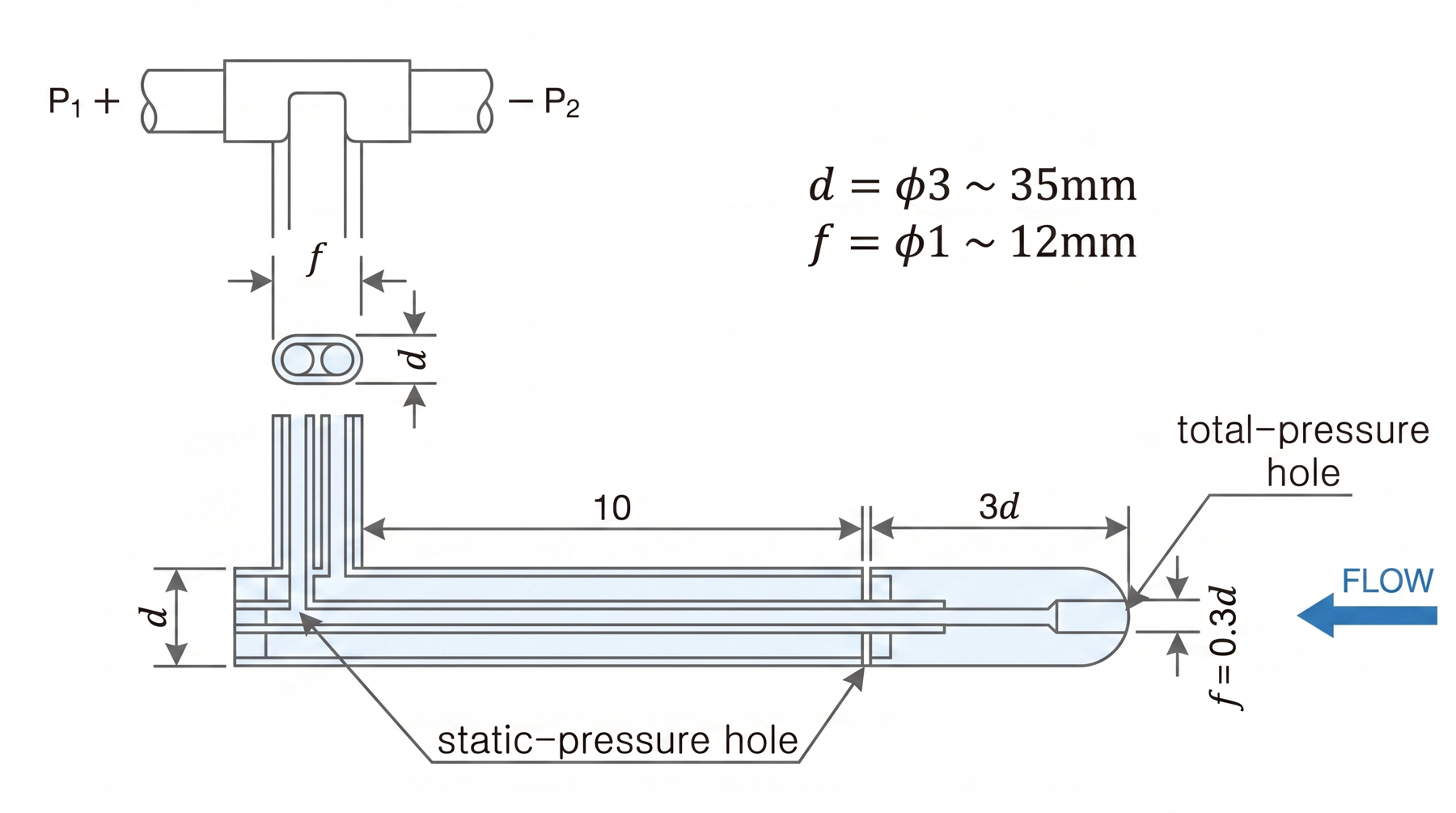
Differential-pressure structure and flow relationship

The velocity of an incompressible fluid is obtained from the Bernoulli equation. Q = A·V = A·√(2g(P₁ − P₂)/r) … Eq. (1). P₁: total pressure, P₂: static pressure, V: velocity, A: pipe cross-sectional area, r: specific gravity.
In practice, the velocity/pressure coefficient C obtained from experimental data is applied, and the flow is calculated as Q = A·V = A·C·√(2g(P₁ − P₂)/r) … Eq. (2).
Taking the velocity profile in the pipe (Figure 2) into account, the sensing holes are placed at the equal-area division positions rᵢ/R. n = 2: 0.5, 0.866 / n = 3: 0.408, 0.707, 0.912 / n = 4: 0.354, 0.612, 0.790, 0.936.
Specification comparison by model


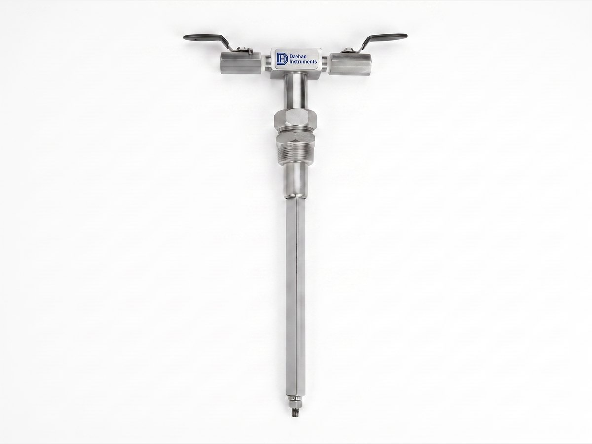
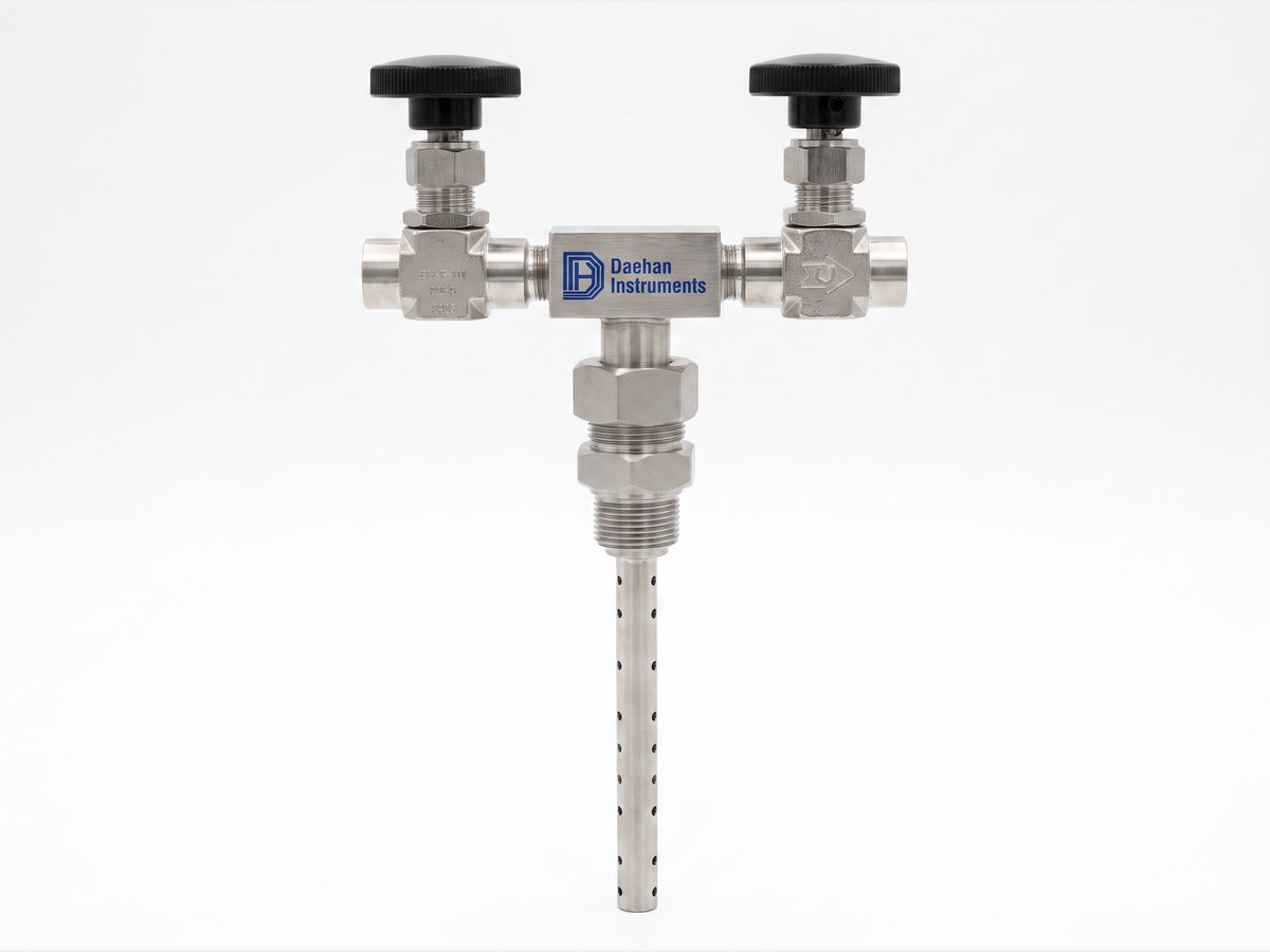
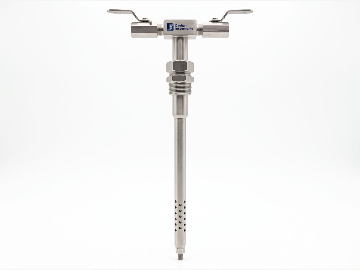
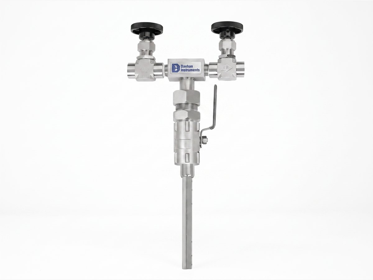
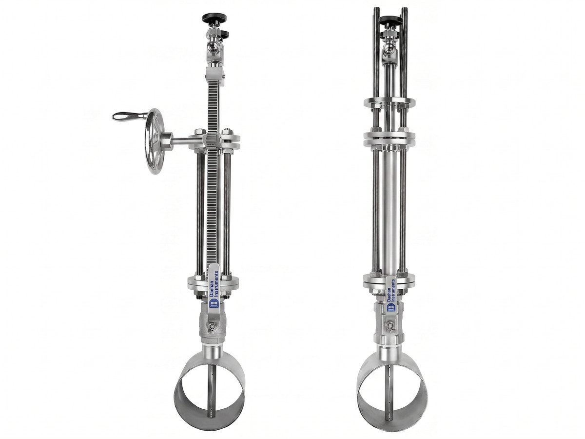
Photographic images by type. Connection sizes, materials and other details follow the ordering code.

| Item | 301 TYPE Single support type (Single support) | 302 TYPE Double support type (Double support) | 303 TYPE Isolation valve type | 304 TYPE Isolation valve & Rod type |
|---|---|---|---|---|
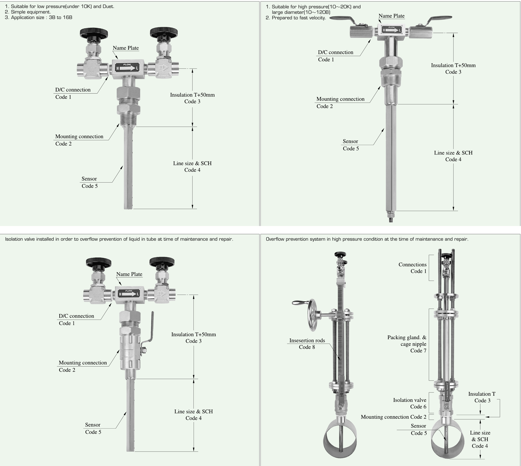
| Features | Easy to install | Suitable for large caliber (suitable for large pipe sizes) | Shut-off fluid after remove element on maintenance (fluid is shut off after removing the element for maintenance) | Installation & maintenance can be done in operation (installation and maintenance possible during operation) |
| Type | Single support type — suitable for low pressure (10K or less) and ducts, simple construction, applicable sizes 3B ~ 16B | Double support type — suitable for high pressure (10 ~ 20K) and large pipe sizes (10 ~ 120B), handles high velocities | Isolation Valve type — fitted with an isolation valve to prevent liquid overflow from the tube during maintenance and repair | Isolation valve & Rod type — overflow prevention system for maintenance and repair under high-pressure conditions (insertion rod · packing gland · cage nipple) |
| Applicable piping | 3B ~ 16B Pipe & Duct | 10B ~ 120B Pipe & Duct | 3B ~ 16B Pipe & Duct | 3B ~ 16B Pipe & Duct |
| Materials | STS316, Inconel, Monel, Hastelloy | STS316, Inconel, Monel, Hastelloy | STS316, Inconel, Monel, Hastelloy | STS316, Inconel, Monel, Hastelloy |
| Connection | Screw & Flange | Screw & Flange | Screw & Flange | Screw & Flange |
| Measured fluid | Liquid & Gas not included sludge (not for high-viscosity fluids) | Liquid & Gas not included sludge (not for high-viscosity fluids) | Liquid & Gas not included sludge (not for high-viscosity fluids) | Liquid & Gas not included sludge (not for high-viscosity fluids) |
| Accuracy | ±1.5% | ±1.5% | ±1.5% | ±1.5% |
Detailed conditions are confirmed at quotation.
| Item | Value |
|---|---|
| Accuracy | ±1.5% |
| Measured fluid | Liquids and gases not containing sludge (not for high-viscosity fluids) |
| Applicable pipe sizes | 301 / 303 / 304 TYPE: 3B ~ 16B · 302 TYPE: 10B ~ 120B (Pipe & Duct) |
| Pressure classes | Single support type (301): low pressure (10K or less) and ducts · double support type (302): high pressure (10 ~ 20K), high velocity |
| Sensor material | STS316, Inconel, Monel, Hastelloy |
| Mounting connection | Screw & Flange ※ Ordering codes: PT1", PT1-1/2, PT2" · JIS 10K / 20K 40A · 50A · 80A · ANSI 150# / 300# 1-1/2B · 2B · 3B |
| DP (D/P) connection | PT 1/2 · PT 3/8 · PT 1/4 |
| Differential-pressure characteristics | About 2 ~ 3 times the differential pressure of a conventional pitot tube · pressure sensed at 4 ~ 8 points inside the pipe |
| Energy | 5 ~ 8% better than an orifice meter |
| Isolation valve material (Body / Ball) | SCPH2/316 · SCPH13/316 · 304/316 · 316/316 · Option (303, 304 TYPE) |
| Packing · cage nipple · insertion rod material | Packing: Rubber, Teflon, Graphite / Cage Nipple: Carbon steel, Stainless steel / Insertion Rods: Carbon steel, Stainless steel (304 TYPE) |
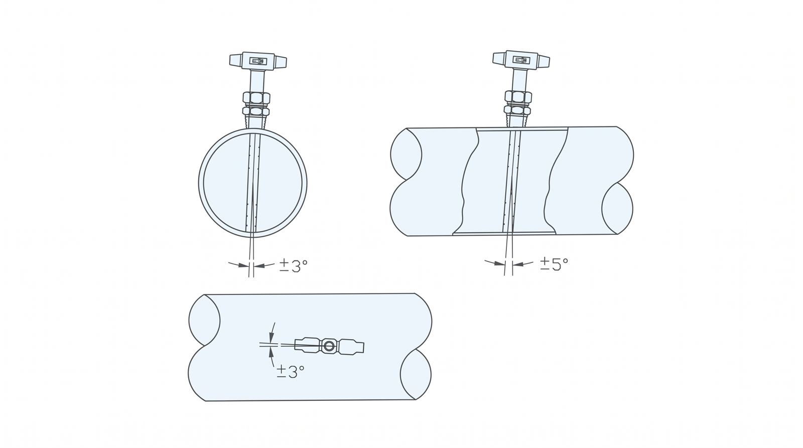
| Installation angle tolerance | Tilt within the pipe cross-section ±3° · tilt along the pipe axis ±5° · sensing hole orientation ±3° |

Unit: mm. Actual manufacturing dimensions are based on the approved drawing.

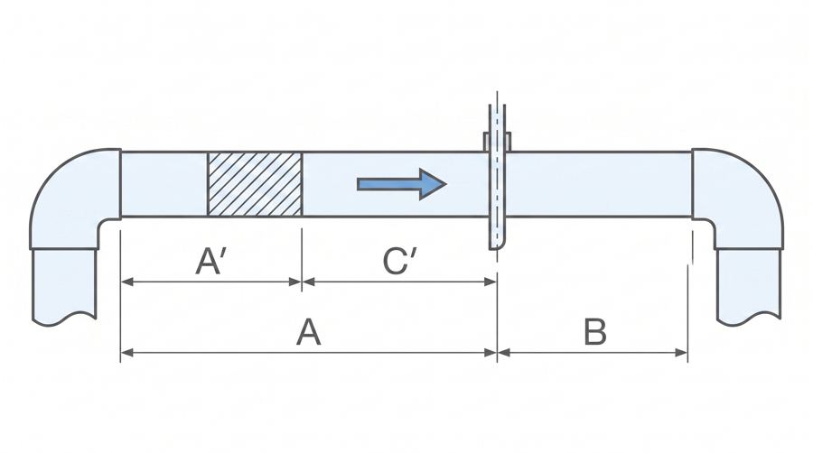
| Upstream piping condition | Without conditioner | With conditioner | Downstream | |||
|---|---|---|---|---|---|---|
| Piping condition | A (same plane) | A (different planes) | A′ | A | C′ | B |
Single 90° elbow | 7 | 9 | 6 | 3 | 3 | 3 |
Two 90° elbows (same plane) | 9 | 14 | 8 | 4 | 4 | 3 |
Two 90° elbows (different planes) | 19 | 24 | 9 | 4 | 5 | 4 |
Reducer | 8 | 8 | 8 | 4 | 4 | 3 |
Expander | 8 | 8 | 8 | 4 | 4 | 3 |
Valve | 24 | 24 | 9 | 4 | 5 | 4 |
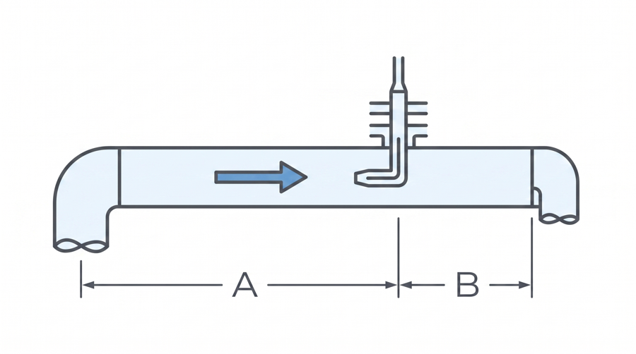
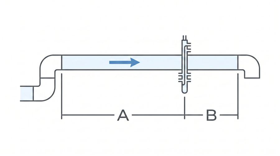
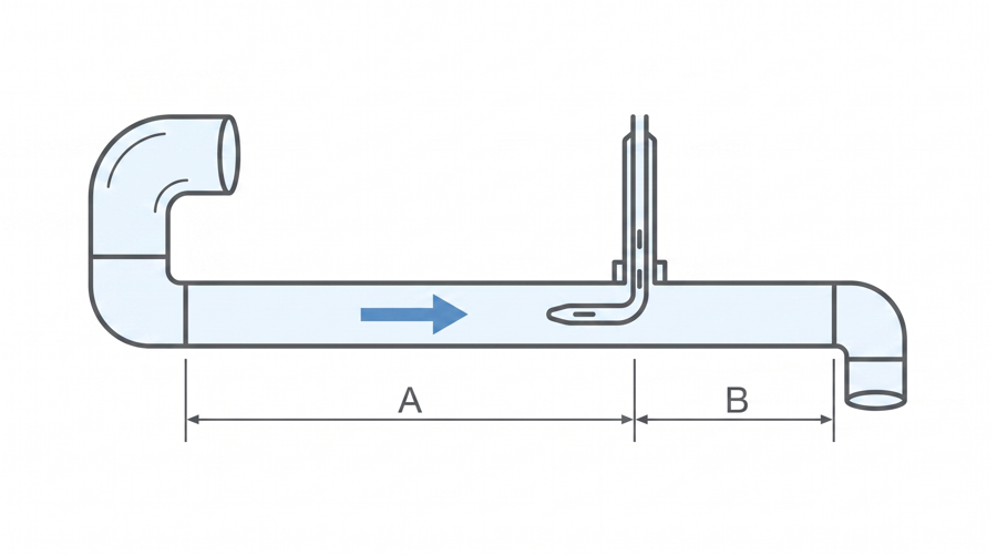
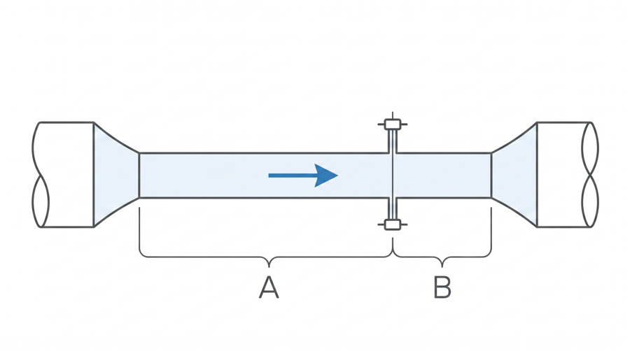
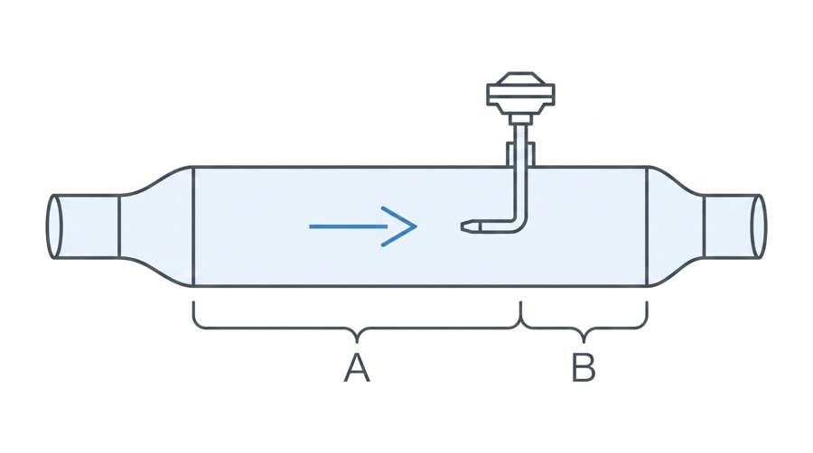
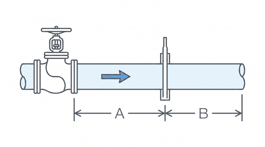
A: upstream straight run, B: downstream straight run, A′ / C′: with a flow conditioner, upstream of the conditioner / conditioner to pitot tube. Figures: A = upstream straight run, B = downstream straight run, A′ = elbow to flow conditioner, C′ = conditioner to pitot tube (unit: multiples of pipe inner diameter D).
| n | r₁ | r₂ | r₃ | r₄ | r₅ |
|---|---|---|---|---|---|
| 2 | 0.5 | 0.866 | – | – | – |
| 3 | 0.408 | 0.707 | 0.912 | – | – |
| 4 | 0.354 | 0.612 | 0.790 | 0.936 | – |
n: number of radial divisions, rᵢ/R: ratio of the sensing point position to the pipe radius.

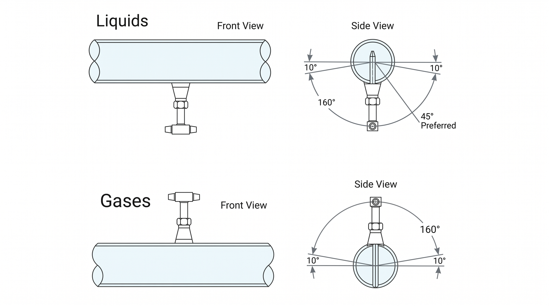
| Fluid | Installation position | Allowable range (side view) |
|---|---|---|
| Liquids | Inserted from the bottom of the pipe | Within 10° either side of vertical (excluding the 160° range), 45° preferred (Preferred) |
| Gases | Inserted from the top of the pipe | Within 10° either side of vertical (excluding the 160° range) |
The diagrams in Pitot Tube catalog p.5 Figure 6 (Liquids) and Figure 7 (Gases), arranged as a table.
Straight run and installation notes
You can request a quotation by combining the model codes.
| 301 | Single support type |
| 302 | Double support type |
| 303 | Isolation Valve type |
| 304 | Isolation valve & Rod type (Isolation valve & Rod type) |
| 2 | PT 1/2 |
| 8 | PT 3/8 |
| 4 | PT 1/4 |
| 1 | PT 1" |
| 2 | PT 1-1/2 |
| 3 | PT 2" |
| 4 | 10K 40A |
| 5 | 10K 50A |
| 6 | 10K 80A |
| 7 | 20K 40A |
| 8 | 20K 50A |
| 9 | 20K 80A |
| 10 | 150# 1-1/2B |
| 11 | 150# 2B |
| 12 | 150# 3B |
| 13 | 300# 1-1/2B |
| 14 | 300# 2B |
| 15 | 300# 3B |
| 0 | Option |
| □□□ | Insulation thickness (T) + 50mm (301, 302 series) |
| □□□ | Pipe size & SCH or pipe inside diameter (original: Line size & SCH or Line India) |
| 5 | STS304 (standard) |
| 6 | STS316 |
| 7 | STS316L |
| 8 | Inconel |
| 9 | Hastelloy |
| 0 | Option |
| 1 | SCPH2 / 316 |
| 2 | SCPH13 / 316 |
| 3 | 304 / 316 |
| 4 | 316 / 316 |
| 5 | Option |
| R | Packing: Rubber |
| T | Packing: Teflon |
| G | Packing: Graphite |
| O | Packing: Option |
| C | Cage Nipple: Carbon steel |
| S | Cage Nipple: Stainless steel |
| O | Cage Nipple: Option |
| C | Carbon steel |
| S | Stainless steel |
| ★ | e.g. Handle (304 TYPE) |
301 - PT1/4 - PT1 - 150 - STPG38 8B SCH40 (or 203.5) - STS304Product Catalog PDF
Printable datasheet with the specifications, dimensions and ordering information on this page (same content as the web page, generated automatically)
Pitot tube overview · measuring principle · features · precautions · installation method · straight run table (Table 4) · allowable limits · ordering method by type (301 ~ 304) · ordering code table · 11 pages
p.7 Average Pitot Tube 301 / 302 / 303 / 304 TYPE· 23p
Other models in the same product family
Tell us the pipe size, fluid, pressure / temperature and flow range, and we will propose a suitable model and a flow calculation sheet.
Contact us online ✉ [email protected] (Sales)Tel 031-357-8431 (Sales, ext. 1) · Fax 031-357-8432