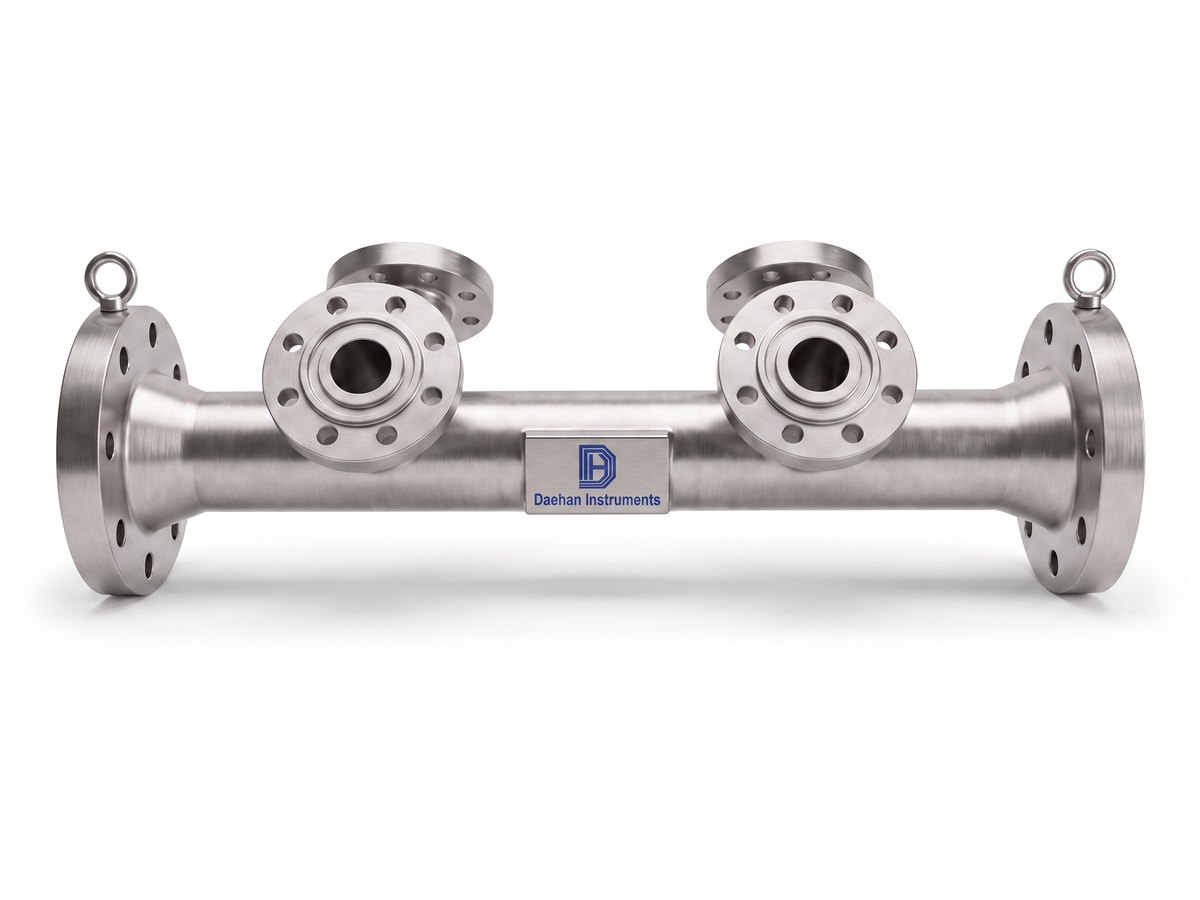
โนซเซิลเวนทูรี (Venturi Nozzle)

รูปทรงหน้าตัดของโนซเซิลเวนทูรีสมมาตรรอบแกน ประกอบด้วยส่วนหดตัวโปรไฟล์โค้งมน คอทรงกระบอก (throat) และส่วนขยาย ผิวด้านต้นน้ำเหมือนโนซเซิล ISA 1932 คอประกอบด้วยส่วน E ยาว 0.3d เหมือนโนซเซิล ISA 1932 และส่วน E′ ยาว 0.4d ~ 0.45d
เส้นผ่านศูนย์กลางคอ d คือค่าเฉลี่ยของการวัดเส้นผ่านศูนย์กลางอย่างน้อย 4 ค่าที่กระจายในมุมเกือบเท่ากันบนระนาบแนวแกน คอต้องเป็นทรงกระบอก และเส้นผ่านศูนย์กลางของหน้าตัดใด ๆ ต้องไม่เบี่ยงเบนจากเส้นผ่านศูนย์กลางเฉลี่ยเกิน 0.05% ส่วนขยายต่อกับส่วน E ของคอโดยไม่มีการลบมุม แต่ต้องขจัดครีบ (burr) ออก
มุมรวม Φ ของส่วนขยายไม่เกิน 30° และโนซเซิลเวนทูรีสามารถตัดสั้น (truncate) ได้ในลักษณะเดียวกับท่อเวนทูรีแบบคลาสสิก
The profile of the Venturi nozzle is axisymmetric. It consists of a convergent section, with a rounded profile, a cylindrical throat and a divergent. The upstream face is identical with that of an ISA 1932 nozzle. The Throat consists of a part E of length 0.3d which is the same as for the ISA 1932 nozzle and a part E' of a length 0.4d to 0.45d. The value d of the diameter of the throat shall be taken as the mean of measurements of at least four diameters distributed in axial planes and at approximately equal angles to each other. The throat shall be cylindrical. No diameter of any cross-section shall differ by more than 0.05% from the value of the mean diameter. This requirement is considered as satisfied when the deviations in the length of any of the measured diameters comply with the said requirement in respect of deviation from the mean. The divergent section shall be connected with the part E of the throat without a rounded part, but any burrs shall be removed. The included angle of the divergent section, Φ, shall be less than or equal to 30°. The Venturi nozzle may be truncated in the same way as the classical venturi tube.
โครงสร้างการเกิดความดันแตกต่างและความสัมพันธ์กับอัตราการไหล
โนซเซิลเวนทูรีประกอบด้วยส่วนหดตัวโปรไฟล์โค้งมน (ผิวด้านต้นน้ำเหมือนโนซเซิล ISA 1932) → คอทรงกระบอก (E: 0.3d, E′: 0.4d ~ 0.45d) → ส่วนขยายที่มีมุมรวมไม่เกิน 30°
หาอัตราการไหลจากความดันแตกต่างระหว่างความดันสูงด้านต้นน้ำของส่วนหดตัวกับความดันต่ำที่คอ และเนื่องจากความดันฟื้นตัวในส่วนขยาย การสูญเสียความดันถาวรจึงน้อยกว่าโนซเซิลเดี่ยวที่มี β เท่ากัน
เปรียบเทียบข้อมูลจำเพาะตามรุ่น

| รายการ | DHOV-N-TM แบบต่อด้วยเกลียวนอก | DHOV-N-TF แบบต่อด้วยเกลียวใน | DHOV-N-BW แบบต่อด้วยการเชื่อมชน | DHOV-N-FL แบบต่อด้วยหน้าแปลน |
|---|---|---|---|---|
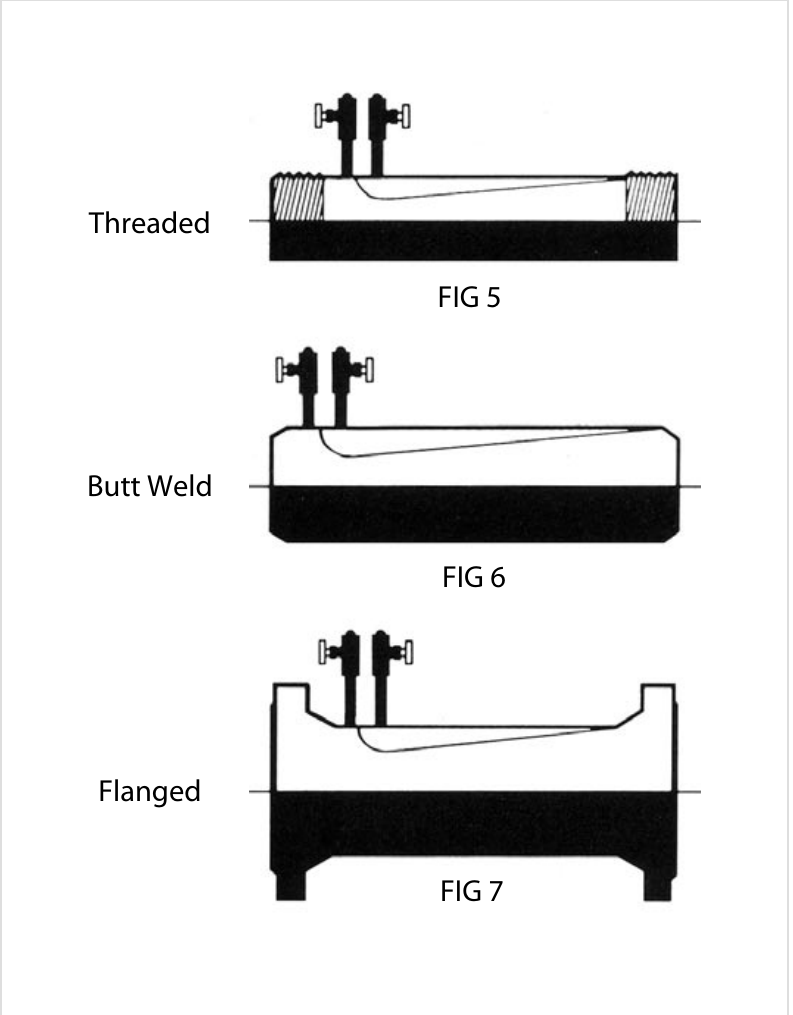
| คุณสมบัติ | Male screw mounting type (Threaded type, FIG 5) | Female screw mounting type (Threaded type, FIG 5) | Butt welding mounting type (Butt weld type, FIG 6) | Flange mounting type (Flanged type, FIG 7) |
| Turndown | 6:1 | 6:1 | 6:1 | 6:1 |
| วัสดุ | Carbon Steel, STS304, STS316, Inconel, Monel, Hastelloy | Carbon Steel, STS304, STS316, Inconel, Monel, Hastelloy | Carbon Steel, STS304, STS316, Inconel, Monel, Hastelloy | Carbon Steel, STS304, STS316, Inconel, Monel, Hastelloy |
| การเชื่อมต่อ | Screw 1/2B ~ 2B (15A ~ 50A) | Screw 1/2B ~ 2B (15A ~ 50A) | Butt Weld | Flange 150#, 300#, 600#, 900#, 1500#, 2500# |
| ท่อที่ใช้ได้ | 1/2B ~ 2B (15A ~ 50A) Pipe | 1/2B ~ 2B (15A ~ 50A) Pipe | 2B ~ 120B (50A ~ 3000A) Pipe | 2B ~ 120B (50A ~ 3000A) Pipe |
| มาตรฐานที่ใช้ | ISO5167-3 | ISO5167-3 | ISO5167-3 | ISO5167-3 |
| ความแม่นยำ | ±2.0% | ±2.0% | ±2.0% | ±2.0% |
เงื่อนไขโดยละเอียดจะกำหนดเมื่อเสนอราคา
| รายการ | ค่า |
|---|---|
| ความแม่นยำ | ±2.0% |
| Turndown | 6:1 |
| ชนิดการต่อ | Threaded type (FIG 5) · Butt weld type (FIG 6) · Flanged type (FIG 7) |
| มาตรฐานการคำนวณอัตราการไหล | ISO5167, JIS Z 8762, ASME, KS A 0612 |
| คลาสหน้าแปลน | ANSI 150, 300, 600, 900, 1500LB |
| ขนาดท่อที่ใช้ได้ | 0.5 to 120B (15A to 3000A) |
| วัสดุ | Carbon Steel · 304SS, 304L SS, 316SS, 316L SS · Ni, Cr, Mo Alloy Steel (A182 F11 to 91) |
| รูปทรง | ผิวด้านต้นน้ำเหมือนโนซเซิล ISA 1932 · คอ E 0.3d + E′ 0.4d ~ 0.45d · ความเบี่ยงเบนเส้นผ่านศูนย์กลางคอ ≤ 0.05% · มุมรวมส่วนขยาย Φ ≤ 30° · ตัดสั้น (truncate) ได้ |
| จุดต่อแท็ปความดันแตกต่าง | NPT 1/4 · NPT 1/2 · NPT 3/4 · SW 1/2 · SW 3/4 |
หน่วย: mm ขนาดที่ผลิตจริงยึดตามแบบที่ได้รับอนุมัติ
| β | 2. Single 90° bend or tee (flow from one branch only) | 3. Two or more 90° bends in the same plane | 4. Two or more 90° bends in different planes | 5. Reducer 2D to D over 2 length of 1.5D to 3D | 6. Expander 0.5D to D over a length of D to 2D | 7. Globe valve full open | 8. Full bore ball or gate valve fully open | 9. Abrupt symmetrical reduction (diameter ratio ≥ 0.5) | 10. Thermometer pocket or well (≤ 0.03D) | 11. Thermometer pocket or well (0.03D ~ 0.13D) | 12. Downstream fittings (columns 2 to 8) |
|---|---|---|---|---|---|---|---|---|---|---|---|
| 0.20 | 10 (6) | 14 (7) | 34 (17) | 5 | 16 (8) | 18 (9) | 12 (6) | 4 (2) | |||
| 0.25 | 10 (6) | 14 (7) | 34 (17) | 5 | 16 (8) | 18 (9) | 12 (6) | 4 (2) | |||
| 0.30 | 10 (6) | 16 (8) | 34 (17) | 5 | 16 (8) | 18 (9) | 12 (6) | 5 (2.5) | |||
| 0.35 | 12 (6) | 16 (8) | 36 (18) | 5 | 16 (8) | 18 (9) | 12 (6) | 5 (2.5) | |||
| 0.40 | 14 (7) | 18 (9) | 36 (18) | 5 | 16 (8) | 20 (10) | 12 (6) | 6 (3) | |||
| 0.45 | 14 (7) | 18 (9) | 38 (17) | 5 | 17 (9) | 20 (10) | 12 (6) | 6 (3) | |||
| 0.50 | 14 (7) | 20 (10) | 40 (20) | 6 (5) | 18 (9) | 22 (11) | 12 (6) | 30 (15) | 5 (3) | 20 (10) | 6 (3) |
| 0.55 | 16 (8) | 22 (11) | 44 (22) | 8 (5) | 20 (10) | 24 (12) | 14 (7) | 6 (3) | |||
| 0.60 | 18 (9) | 26 (13) | 48 (24) | 9 (5) | 22 (11) | 26 (13) | 14 (7) | 7 (3.5) | |||
| 0.65 | 22 (11) | 32 (16) | 54 (27) | 11 (6) | 25 (13) | 28 (14) | 16 (8) | 7 (3.5) | |||
| 0.70 | 28 (14) | 36 (18) | 62 (31) | 14 (7) | 30 (15) | 32 (16) | 20 (10) | 7 (3.5) | |||
| 0.75 | 36 (18) | 42 (21) | 70 (35) | 22 (11) | 38 (19) | 36 (18) | 24 (12) | 8 (4) | |||
| 0.80 | 46 (23) | 50 (25) | 80 (40) | 30 (15) | 54 (27) | 44 (22) | 30 (15) | 8 (4) |
คอลัมน์ 2 ~ 11 คือท่อตรงด้านต้นน้ำ (ทางเข้า) คอลัมน์ 12 คือท่อตรงด้านปลายน้ำ (ทางออก) ค่าที่ไม่มีวงเล็บคือค่า 'ความไม่แน่นอนเพิ่มเติม 0' ค่าในวงเล็บคือค่า 'ความไม่แน่นอนเพิ่มเติม 0.5%' ท่อตรงต่ำสุดที่ต้องการคือความยาวระหว่างฟิตติ้งแต่ละตัวทางต้นน้ำ·ปลายน้ำกับอุปกรณ์ปฐมภูมิ และความยาวท่อตรงทั้งหมดวัดจากหน้าด้านต้นน้ำของอุปกรณ์ปฐมภูมิ การติดตั้งพ็อกเก็ต·เวลล์ของเทอร์โมมิเตอร์ไม่เปลี่ยนแปลงท่อตรงต้นน้ำต่ำสุดที่ต้องการสำหรับฟิตติ้งอื่น
ท่อตรงและข้อควรระวังในการติดตั้ง
ท่านสามารถประกอบรหัสรุ่นเพื่อขอใบเสนอราคาได้
| TM | Threaded Male type (แบบเกลียวนอก) |
| TF | Threaded Female type (แบบเกลียวใน) |
| BW | Butt weld type (แบบเชื่อมชน) |
| FL | Flanged type (แบบหน้าแปลน) |
| □□□ | Pipe size in inch or mm (ขนาดระบุของท่อ เป็น inch หรือ mm) |
| CS | Carbon Steel |
| 4S | 304SS |
| 4L | 304L SS |
| 6S | 316SS |
| 6L | 316L SS |
| 11 | A182 F11 |
| 12 | A182 F12 |
| 51 | A182 F51 |
| 91 | A182 F91 |
| OP | Option |
| 015 | ANSI Class 150 LB |
| 030 | ANSI Class 300 LB |
| 060 | ANSI Class 600 LB |
| 090 | ANSI Class 900 LB |
| 150 | ANSI Class 1500 LB |
| NPT □□□ | Threaded (ต่อด้วยเกลียว) |
| 000 | Option |
| 0 | NPT 1/4 |
| 1 | NPT 1/2 |
| 2 | NPT 3/4 |
| 3 | SW 1/2 |
| 4 | SW 3/4 |
| /□□□ | ตัวเลือก (ตกลงแยกต่างหาก) |
แคตตาล็อกผลิตภัณฑ์ PDF
ดาต้าชีทสำหรับพิมพ์ที่มีข้อมูลจำเพาะ ขนาด และข้อมูลการสั่งซื้อของหน้านี้ (เนื้อหาเดียวกับเว็บ สร้างอัตโนมัติ)
แคตตาล็อกโนซเซิลเวนทูรี (DHOV-N) — คำอธิบาย · ข้อมูลจำเพาะ · FIG 5~7 · ตารางท่อตรงที่ต้องการ · รหัสสั่งซื้อ · 3 หน้า
p.13 Venturi Nozzle DHOV-N-TM / TF / BW / FL· 23p
รุ่นอื่นในกลุ่มผลิตภัณฑ์เดียวกัน
เพียงแจ้งขนาดท่อ ของไหล ความดัน·อุณหภูมิ และช่วงอัตราการไหล เราจะเสนอรุ่นที่เหมาะสมพร้อมเอกสารคำนวณอัตราการไหล
ติดต่อออนไลน์ ✉ [email protected] (ฝ่ายขาย)โทร 031-357-8431 (ฝ่ายขาย ต่อ 1) · แฟกซ์ 031-357-8432