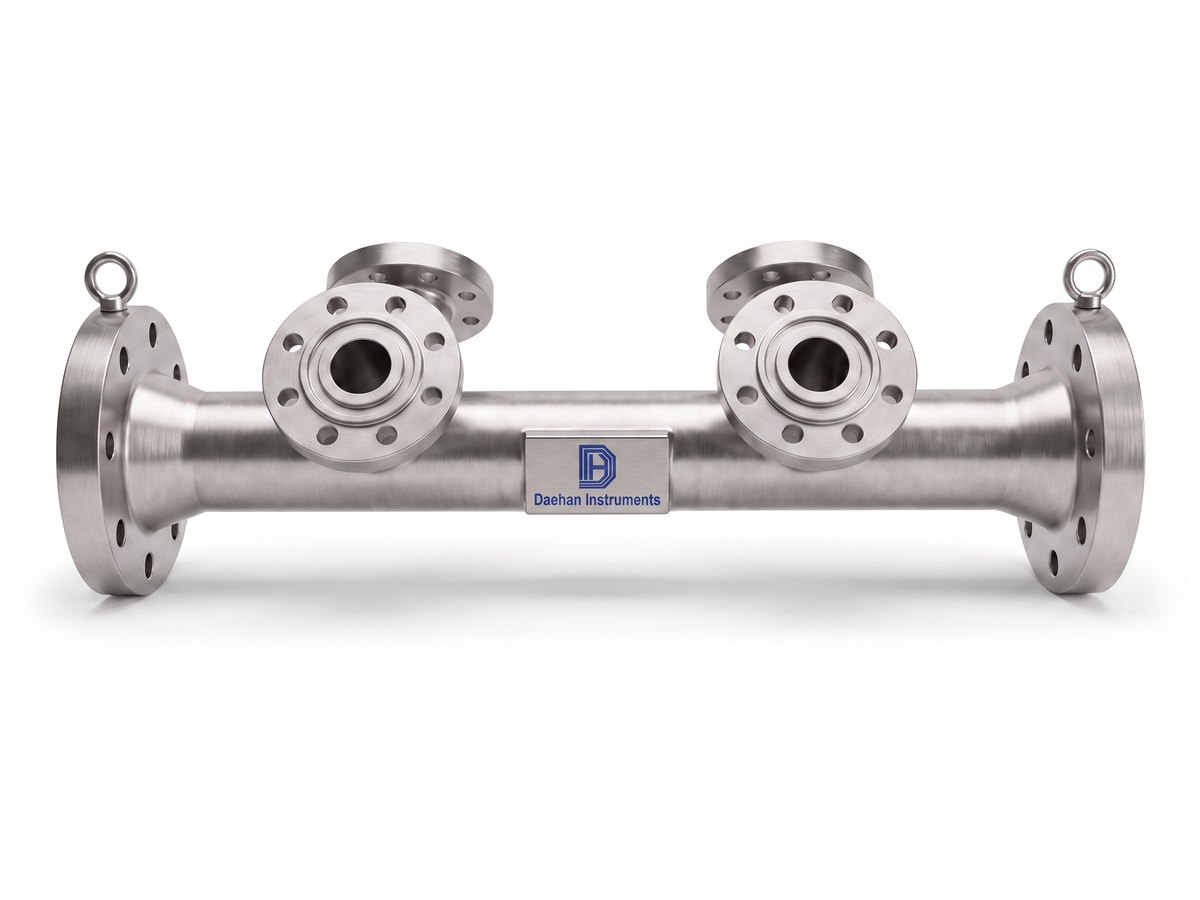
벤투리 노즐 (Venturi Nozzle)

벤투리 노즐의 단면 형상은 축대칭이며, 둥근 프로파일의 수축부, 원통형 목(throat), 확대부로 구성됩니다. 상류면은 ISA 1932 노즐과 동일합니다. 목은 ISA 1932 노즐과 같은 길이 0.3d의 E 부분과 길이 0.4d ~ 0.45d의 E′ 부분으로 이루어집니다.
목 직경 d는 축 방향 평면에서 서로 거의 같은 각도로 분포한 최소 4개 직경 측정값의 평균으로 합니다. 목은 원통형이어야 하며, 어떤 단면의 직경도 평균 직경에서 0.05%를 초과하여 벗어나지 않아야 합니다. 확대부는 목의 E 부분에 라운드 없이 연결하되 버(burr)는 제거합니다.
확대부의 사잇각 Φ는 30° 이하로 하며, 벤투리 노즐은 고전형 벤투리 튜브와 같은 방식으로 절단(truncate)할 수 있습니다.
The profile of the Venturi nozzle is axisymmetric. It consists of a convergent section, with a rounded profile, a cylindrical throat and a divergent. The upstream face is identical with that of an ISA 1932 nozzle. The Throat consists of a part E of length 0.3d which is the same as for the ISA 1932 nozzle and a part E' of a length 0.4d to 0.45d. The value d of the diameter of the throat shall be taken as the mean of measurements of at least four diameters distributed in axial planes and at approximately equal angles to each other. The throat shall be cylindrical. No diameter of any cross-section shall differ by more than 0.05% from the value of the mean diameter. This requirement is considered as satisfied when the deviations in the length of any of the measured diameters comply with the said requirement in respect of deviation from the mean. The divergent section shall be connected with the part E of the throat without a rounded part, but any burrs shall be removed. The included angle of the divergent section, Φ, shall be less than or equal to 30°. The Venturi nozzle may be truncated in the same way as the classical venturi tube.
차압 발생 구조와 유량 관계
벤투리 노즐은 둥근 프로파일의 수축부(ISA 1932 노즐과 동일한 상류면) → 원통형 목(E: 0.3d, E′: 0.4d ~ 0.45d) → 사잇각 30° 이하의 확대부로 이루어집니다.
수축부 상류의 고압과 목의 저압 사이 차압으로 유량을 구하며, 확대부에서 압력이 회복되므로 동일 β의 노즐 단품보다 영구 압력 손실이 작습니다.
모델별 사양 비교

| 항목 | DHOV-N-TM 수나사 연결형 | DHOV-N-TF 암나사 연결형 | DHOV-N-BW 맞대기 용접 연결형 | DHOV-N-FL 플랜지 연결형 |
|---|---|---|---|---|
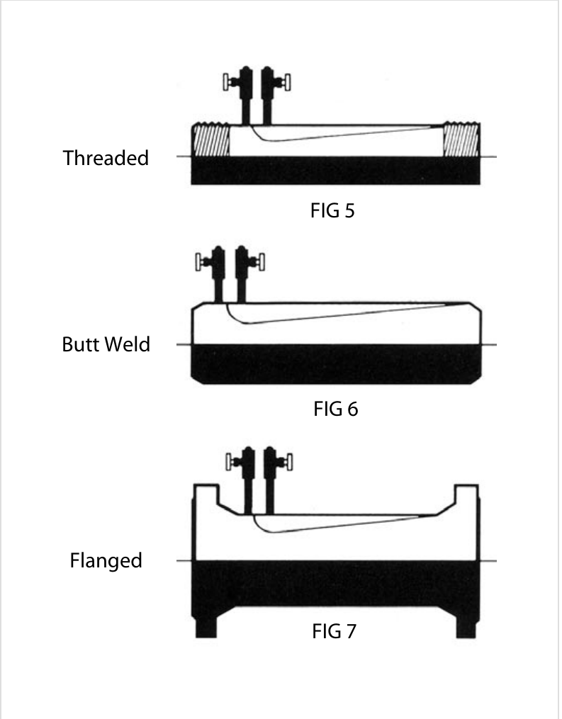
| 특징 | Male screw mounting type (Threaded type, FIG 5) | Female screw mounting type (Threaded type, FIG 5) | Butt welding mounting type (Butt weld type, FIG 6) | Flange mounting type (Flanged type, FIG 7) |
| 턴다운 | 6:1 | 6:1 | 6:1 | 6:1 |
| 재질 | Carbon Steel, STS304, STS316, Inconel, Monel, Hastelloy | Carbon Steel, STS304, STS316, Inconel, Monel, Hastelloy | Carbon Steel, STS304, STS316, Inconel, Monel, Hastelloy | Carbon Steel, STS304, STS316, Inconel, Monel, Hastelloy |
| 연결 | Screw 1/2B ~ 2B (15A ~ 50A) | Screw 1/2B ~ 2B (15A ~ 50A) | Butt Weld | Flange 150#, 300#, 600#, 900#, 1500#, 2500# |
| 적용 배관 | 1/2B ~ 2B (15A ~ 50A) Pipe | 1/2B ~ 2B (15A ~ 50A) Pipe | 2B ~ 120B (50A ~ 3000A) Pipe | 2B ~ 120B (50A ~ 3000A) Pipe |
| 적용 규격 | ISO5167-3 | ISO5167-3 | ISO5167-3 | ISO5167-3 |
| 정확도 | ±2.0% | ±2.0% | ±2.0% | ±2.0% |
상세 조건은 견적 시 확정합니다.
| 항목 | 값 |
|---|---|
| 정확도 | ±2.0% |
| 턴다운 | 6:1 |
| 연결 타입 | Threaded type (FIG 5) · Butt weld type (FIG 6) · Flanged type (FIG 7) |
| 유량 계산 규격 | ISO5167, JIS Z 8762, ASME, KS A 0612 |
| 플랜지 등급 | ANSI 150, 300, 600, 900, 1500LB |
| 적용 관경 | 0.5 to 120B (15A to 3000A) |
| 재질 | Carbon Steel · 304SS, 304L SS, 316SS, 316L SS · Ni, Cr, Mo Alloy Steel (A182 F11 to 91) |
| 형상 | 상류면 ISA 1932 노즐과 동일 · 목 E 0.3d + E′ 0.4d ~ 0.45d · 목 직경 편차 ≤ 0.05% · 확대부 사잇각 Φ ≤ 30° · 절단(truncate) 가능 |
| 차압 탭 연결 | NPT 1/4 · NPT 1/2 · NPT 3/4 · SW 1/2 · SW 3/4 |
단위: mm. 실제 제작 치수는 승인 도면을 기준으로 합니다.
| β | 2. Single 90° bend or tee (flow from one branch only) | 3. Two or more 90° bends in the same plane | 4. Two or more 90° bends in different planes | 5. Reducer 2D to D over 2 length of 1.5D to 3D | 6. Expander 0.5D to D over a length of D to 2D | 7. Globe valve full open | 8. Full bore ball or gate valve fully open | 9. Abrupt symmetrical reduction (diameter ratio ≥ 0.5) | 10. Thermometer pocket or well (≤ 0.03D) | 11. Thermometer pocket or well (0.03D ~ 0.13D) | 12. Downstream fittings (columns 2 to 8) |
|---|---|---|---|---|---|---|---|---|---|---|---|
| 0.20 | 10 (6) | 14 (7) | 34 (17) | 5 | 16 (8) | 18 (9) | 12 (6) | 4 (2) | |||
| 0.25 | 10 (6) | 14 (7) | 34 (17) | 5 | 16 (8) | 18 (9) | 12 (6) | 4 (2) | |||
| 0.30 | 10 (6) | 16 (8) | 34 (17) | 5 | 16 (8) | 18 (9) | 12 (6) | 5 (2.5) | |||
| 0.35 | 12 (6) | 16 (8) | 36 (18) | 5 | 16 (8) | 18 (9) | 12 (6) | 5 (2.5) | |||
| 0.40 | 14 (7) | 18 (9) | 36 (18) | 5 | 16 (8) | 20 (10) | 12 (6) | 6 (3) | |||
| 0.45 | 14 (7) | 18 (9) | 38 (17) | 5 | 17 (9) | 20 (10) | 12 (6) | 6 (3) | |||
| 0.50 | 14 (7) | 20 (10) | 40 (20) | 6 (5) | 18 (9) | 22 (11) | 12 (6) | 30 (15) | 5 (3) | 20 (10) | 6 (3) |
| 0.55 | 16 (8) | 22 (11) | 44 (22) | 8 (5) | 20 (10) | 24 (12) | 14 (7) | 6 (3) | |||
| 0.60 | 18 (9) | 26 (13) | 48 (24) | 9 (5) | 22 (11) | 26 (13) | 14 (7) | 7 (3.5) | |||
| 0.65 | 22 (11) | 32 (16) | 54 (27) | 11 (6) | 25 (13) | 28 (14) | 16 (8) | 7 (3.5) | |||
| 0.70 | 28 (14) | 36 (18) | 62 (31) | 14 (7) | 30 (15) | 32 (16) | 20 (10) | 7 (3.5) | |||
| 0.75 | 36 (18) | 42 (21) | 70 (35) | 22 (11) | 38 (19) | 36 (18) | 24 (12) | 8 (4) | |||
| 0.80 | 46 (23) | 50 (25) | 80 (40) | 30 (15) | 54 (27) | 44 (22) | 30 (15) | 8 (4) |
2 ~ 11열은 상류(입구)측, 12열은 하류(출구)측 직관부. 괄호 없는 값은 '추가 불확도 0' 값, 괄호 안 값은 '추가 불확도 0.5%' 값. 필요 최소 직관부는 상류·하류의 각 피팅과 1차 요소 사이의 길이이며 모든 직관 길이는 1차 요소의 상류면에서 측정. 온도계 포켓·웰의 설치는 다른 피팅에 필요한 최소 상류 직관부를 변경하지 않음.
직관부 및 설치 시 유의사항
모델 코드를 조합해 견적을 요청하실 수 있습니다.
| TM | Threaded Male type (수나사형) |
| TF | Threaded Female type (암나사형) |
| BW | Butt weld type (맞대기 용접형) |
| FL | Flanged type (플랜지형) |
| □□□ | Pipe size in inch or mm (배관 호칭 지름, inch 또는 mm) |
| CS | Carbon Steel |
| 4S | 304SS |
| 4L | 304L SS |
| 6S | 316SS |
| 6L | 316L SS |
| 11 | A182 F11 |
| 12 | A182 F12 |
| 51 | A182 F51 |
| 91 | A182 F91 |
| OP | Option |
| 015 | ANSI Class 150 LB |
| 030 | ANSI Class 300 LB |
| 060 | ANSI Class 600 LB |
| 090 | ANSI Class 900 LB |
| 150 | ANSI Class 1500 LB |
| NPT □□□ | Threaded (나사 연결) |
| 000 | Option |
| 0 | NPT 1/4 |
| 1 | NPT 1/2 |
| 2 | NPT 3/4 |
| 3 | SW 1/2 |
| 4 | SW 3/4 |
| /□□□ | 옵션 (별도 협의) |
같은 제품군의 다른 모델
배관 구경, 유체, 압력·온도, 유량 범위를 알려주시면 적합한 모델과 유량 계산서를 제안해 드립니다.
온라인 문의하기 ✉ [email protected] (영업부)전화 031-357-8431 (영업부 내선 1) · 팩스 031-357-8432